Tutorial 3: Cooling circuit model of a High-Pressure Turbine (HPT) Nozzle
Purpose/Objective
This exercise will walk the user through building a portion of the cooling circuit of a High-Pressure Turbine (HPT) Nozzle. The user will learn how to:
- Edit chamber properties
- Edit element properties
- Check the model
- Run the model
- Post-process the model
- Chamber Types: Plenum, Momentum
- Element Types: Standard Tube, Conventional Orifice,
- Fluid: Air
Step 1: Examine geometry and create plan
- The user will be creating a model of an air-cooled HPT nozzle as shown in figure 1.01. The HPT nozzle is exposed to air heated to high temperature by combustion just upstream. This is an example model of how the nozzle could be cooled to keep the material temperature within limits.
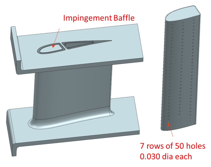
Figure 1.01: HPT Nozzle
- Cooling air comes in through the bottom of the leading edge cavity and pressurizes the inside of the baffle, pushing the air through the impingement holes, and then exits through the gap between the baffle and the inside wall of the leading edge cavity at the top of the nozzle (shown in Figure 1.02)
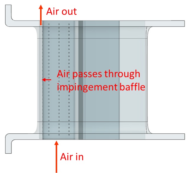
Figure 1.02: Cooling air flow path
- To model cooling flow, the user will primarily be making use of tube and conventional orifice elements
Step 2: Load IGES file
- Go to File → Load IGES File
- Browse to IGES location and select open (nozzle_model.igs)
Figure 1.03: Loaded IGES file
Step 3: Building Model
- Plan model setup based on what is known about the geometry

Figure 1.04: Sketch/Outline of LE cavity
- Drag and drop Boundary Plenum chambers at the inlet and outlet locations from Figure
1.04
- Translate (right click chamber/element → translate) option and manually editing the coordinates(Property Editor → Location), can be used to assist in placing chambers and elements in the right location
- Use
 to adjust symbol and text size
 - Create a datum plane at the location of the first layer, so that chambers and
elements can easily be placed on the same plane (Optional)
- Go to PreProcessing → Datum Planes to bring up the Datum planes tab
- Click Create, name it Layer 1, and set the Z Reference Point to 0.3
- Click Save and check the box next to it to make it current (Figure 1.05)
- Unchecking the “Current” checkbox will enable the user to place chambers and elements anywhere on the model again
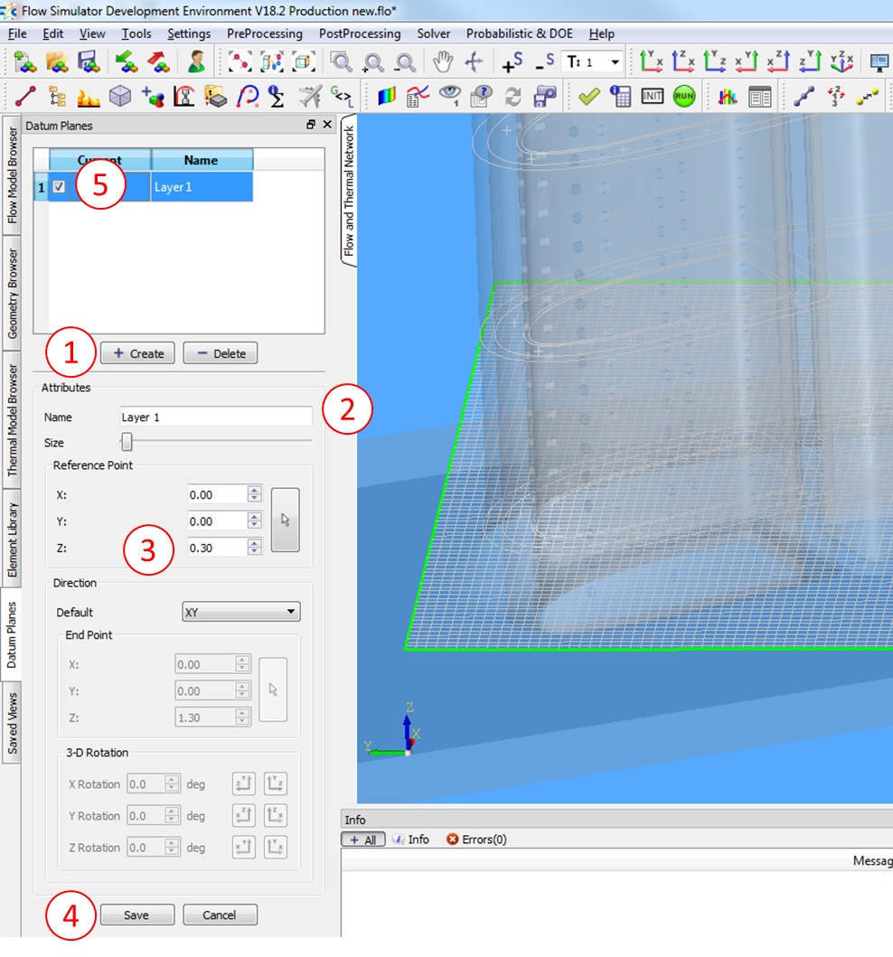
Figure 1.05: Creating a Datum Plane can help with placing Chambers and Elements on the same plane
- Place non boundary momentum chambers around the inlet LE cavity as shown in Figure
1.04
- Pressing and holding “Shift” while dragging chambers and elements enables snapping to IGES vertices for easier placement (Figure 1.06)
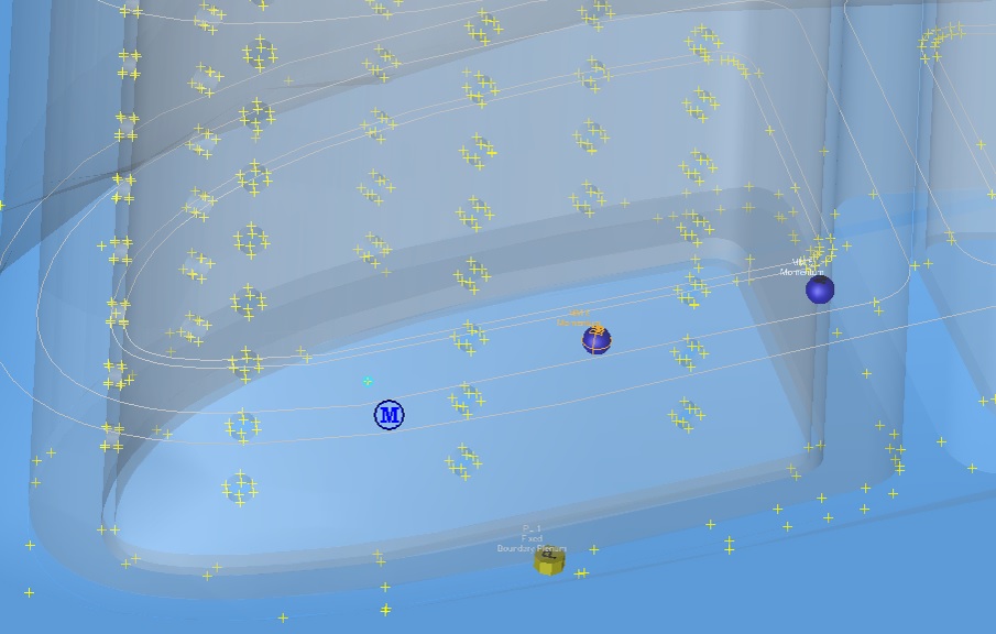
Figure 1.06: Snapping to IGES vertices
- Place a non-boundary momentum chamber at the center of the LE cavity
- Connect the momentum chambers between the baffle and the LE walls with Standard tubes. The direction of these tubes is hard to predict, but the Flow Simulator solver is able to reverse the flow direction if needed. You can create the tubes in the direction shown in Figure 1.04 or you can use your own directions.
- Connect the single momentum chamber at the center of the cavity to the momentum chambers between the baffle and LE wall with Conventional Orifice elements
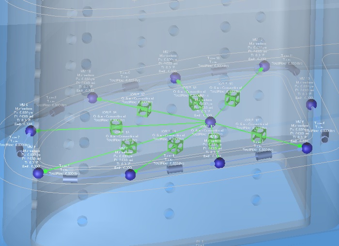
Figure 1.07: Chamber and Element set-up of bottom layer
- Select all tube elements and switch Geometric Input Choice from Hyd Diameter to
Area
- Set Area to 0.051 in^2
- Set Length to 0.2788 in
- Set Hide Advanced Options → Heat Addition → Wall Temperature to 800 F. This is to simulate some heat transfer to hot metal. The 800F is an estimate of the average metal temperature surrounding the tube. A more accurate method would be to create a thermal network to model the heat transfer.
- Select all Conventional Orifice Elements and switch Area/Diameter to Diameter
- Set Diameter to 0.03 in
- Set Cd to 0.8
- Set Hide Advanced Options → Element Multiplicity → No. of Streams Entering and Exiting to 10
- Set Hide Advanced Options → Element Orientation → Element Inlet Orientation to Other and set Tangential Angle to 180 degrees
- Now that the first layer set-up is complete, the translate option can be used to
copy and position the next layer of chambers and elements (make sure to uncheck
“Current” from the datum plane tab if a datum plane was used for the chamber and
element placement)
- Select all chambers and elements in the first layer and Right Click → Translate
- Press the down arrow
 under “Auto Control” on the small box that pops
up
under “Auto Control” on the small box that pops
up - Set Direction of Translation to Global Z Direction
- Enter a distance of 0.6 in
- Change “No Copy” to “Copy to group” from the dropdown and click Execute
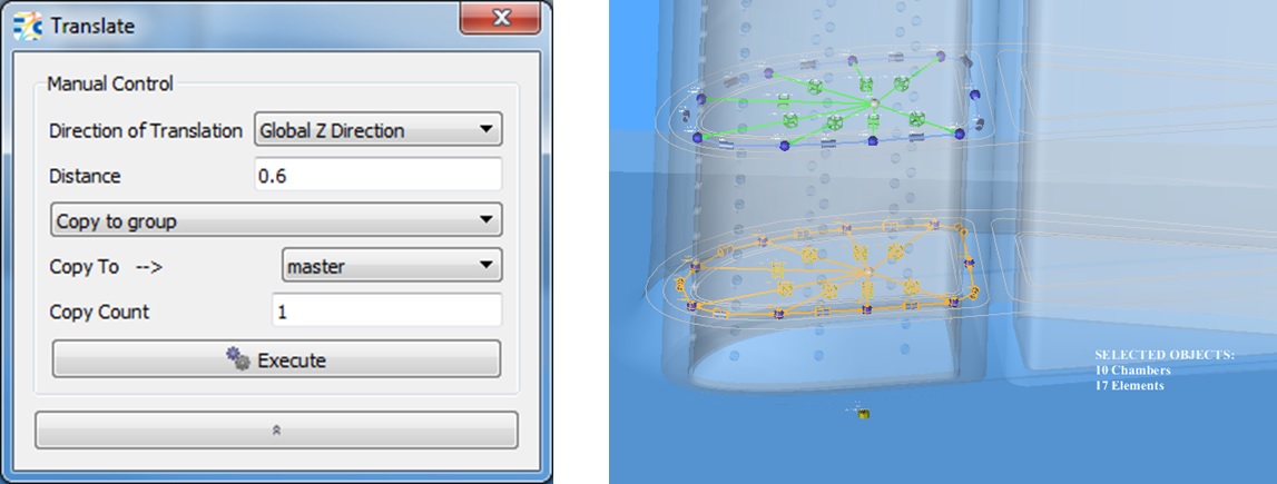
Figure 1.08: Copying chambers and elements using Translate
- Connect the outside momentum chambers from layer one to their respective momentum
chamber in layer two using Standard Tube elements
- After placing and connecting the element, one way of aligning it with the rest of the model is by copying the X and Y coordinates from the connected chambers and setting the Z coordinate to 0.6
- For the connecting tubes between layer one and two
- Switch Geometric Input Choice from Hyd Diameter to Area and set Area to 0.023 in
- Set Length to 0.6 in
- Set Wall Temperature to 800 F
- Set Hide Advanced Options → Element Orientation → Element Inlet Orientation to Radial Outward
- Select the chambers and elements in layers one and two and Translate/Copy them to
layers three and four
- Select all chambers and elements and Right Click → Translate
- Press the down arrow under “Auto Control” on the small box that pops
up
- Set Direction of Translation to Global Z Direction
- Enter a distance of 1.2 in
- Change “No Copy” to “Copy to group” from the dropdown and click Execute
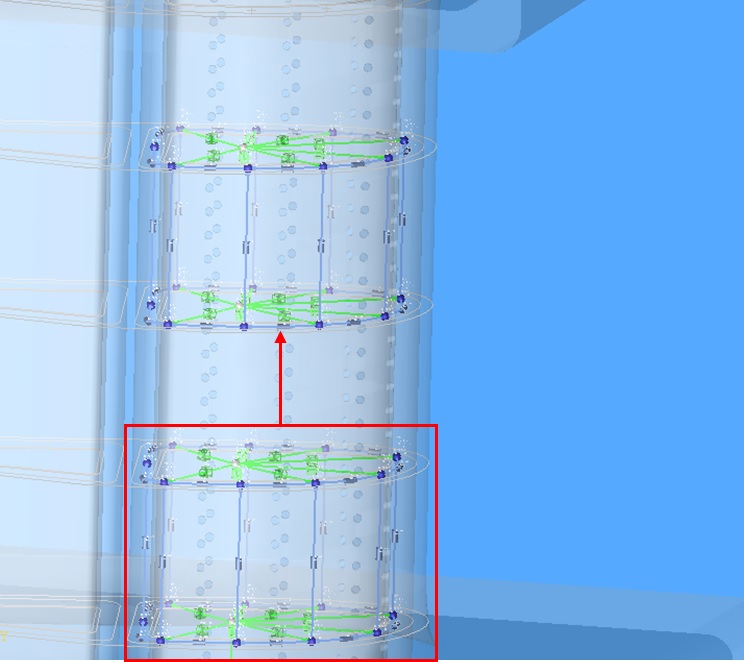
Figure 1.09: Copying layers 1 & 2 to layers 3 & 4
- Connect layers two and three using the same method and inputs as layers one and two
- Select the chambers and elements in layer four and Translate/Copy them to layer
five
- Select all chambers and elements and Right Click → Translate
- Press the down arrow under “Auto Control” on the small box that pops
up
- Set Direction of Translation to Global Z Direction
- Enter a distance of 0.6 in
- Change “No Copy” to “Copy to group” from the dropdown and click Execute
- Connect layers four and five using the same method and inputs as layers one and two
- Connect layer five momentum chambers to the Boundary Plenum using tube elements
- Use the same inputs as the connecting elements used previously, but set Length to 0.3 in (half of 0.6 in)
- Connect the Inlet Boundary Plenum to the momentum chamber at the center of the first
layer with a Conventional Orifice Element
- Set Area to 0.2876 in^2
- Set Hide Advanced Options → Element Orientation → Element Inlet Orientation to Radial Outward
- Connect the remaining non-boundary momentum chambers at the center of the cavity using the same method and inputs as the first one
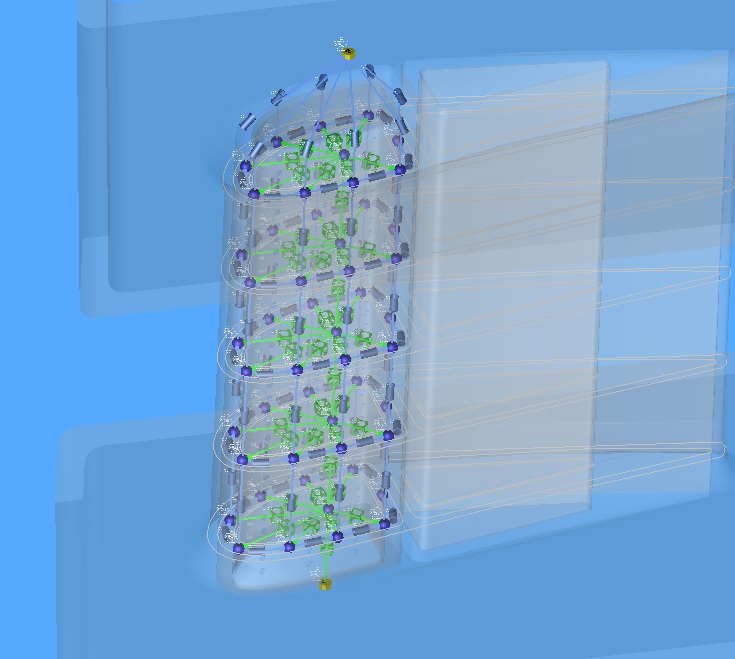
Figure 1.10: Finished model layout
- Set inlet Boundary Plenum Static Pressure to 500 psi and Temperature to 500 F
- Set outlet Boundary Chamber Static Pressure to 400 psi and Temperature to 500 F
Step 4: Check Model and Run
- Select checkmark icon from the top toolbar
 to check the model for warnings/errors.
- An error should populate stating that the internal chamber has not been initialized
- Select the initialization icon from the toolbar
 , and pick Start. Accept values once flow solver has
converged.
, and pick Start. Accept values once flow solver has
converged. - Select run icon from toolbar
 . Run Flow Simulator.
Step 5: Post-process
- Results file (*.res) should automatically be loaded into GUI. If not, it can be selected via File → Load Result File
- By default, both chamber and elemental results are displayed in the graphical workspace.
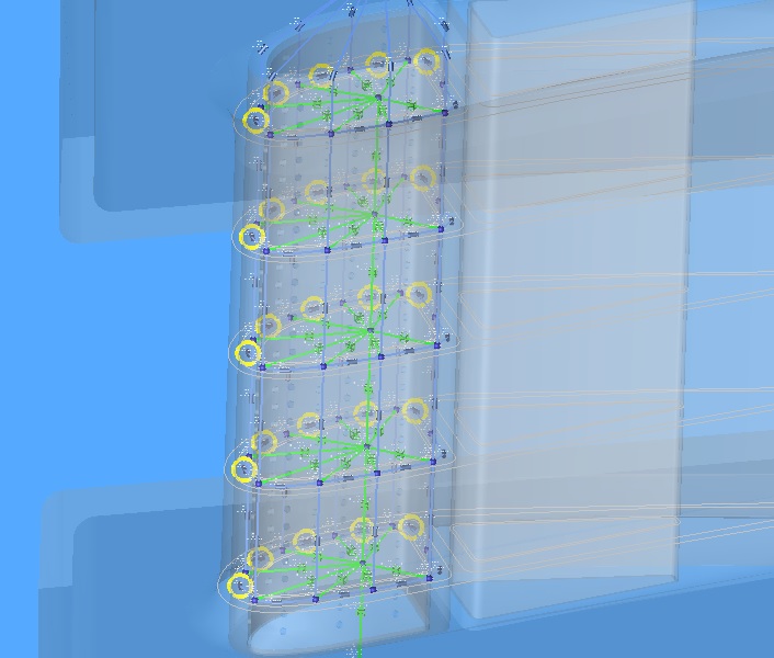
Figure 1.11: Reverse flow indicators
- The yellow circles around some of the elements (Figure 1.11) are indicating that the direction of flow is opposite to the orientation of the element