Defining a Schematic Link
Define a connection(s) between circuit elements (defined in a cable schematic view) and the full wave model.
Note: Only applicable to shielded cables solved with the MoM/MTL solution method.
-
On the Cables tab, in the
Create Instance group, click the
 Schematic link
icon.
Schematic link
icon.
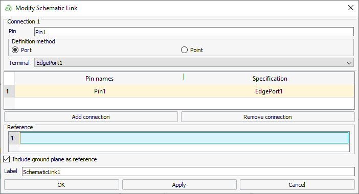
- In the Pin name field, specify the name of the pin. This pin is the transitioning point from circuit elements (defined in the cable schematic view) to the full wave model.
-
Under Definition method, select one of the following
options for each connection:
-
- Port
- In the Terminal field, select a
defined port from the drop-down list or
create a new port. The positive port terminal is exposed on
the schematic as a circuit node. The negative port terminal
should coincide with the reference surface.Note: The defined port is limited to wire/edge ports.
-
- Point
- Under Point, specify the coordinates of the point that is exposed on the schematic as a circuit node.
Note: The physical connection is not indicated in the 3D view. -
-
[Optional] Under Reference, specify the face(s) defining
the common reference surface that translates to a single node of reference on
the cable schematic view.
Note:
- If one of the connections references a port, a reference face is required.
- If none of the connections references a port, a reference face is optional.
- Select the Include ground plane as reference check box to include a PEC infinite ground plane as part of the reference surface.
- In the Label field, add a unique label for the schematic link.
- Click Create to create the schematic link and to close the dialog.
- Circuit connections between the cable path connector pins and the schematic link connector pins can be added to the schematic view.