Defining a Shielded Enclosure
Define a shielded enclosure that allows the outermost shield signals of different cable paths in a combined MoM/MTL cable harness to be connected to a shielded conductive enclosure defined in the full wave (3D) model.
-
On the Cables tab, in the
Create Instance group, click the
 Shielded Enclsoure icon.
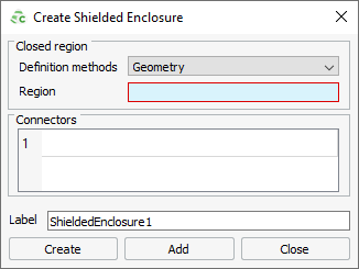
Figure 1. The Create Shielded Enclosure dialog.
-
From the Definition methods
drop-down list, select one of the following options:
- To connect the shielded enclosure to a geometry model, select Geometry. In the details tree, click on the region of the shielded enclosure.
- To connect the shielded enclosure to the mesh face(s) of a model mesh, select Mesh. In the details tree, under Triangle Labels, click on a face or faces.
- Under Connectors, specify the connectors related to the cable paths that terminate on the shielded enclosure by clicking on the connector(s) in the model tree.
- In the Label field, add a unique label for the shielded enclosure.
- Click Create to create the shielded enclosure and to close the dialog.