Defining Cable Connectors
Create a cable connector at the end terminal of a cable.
-
On the Cables tab, in the
Create Instance group, click the
 Cable Connector icon.
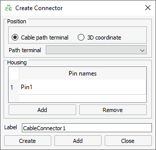
Figure 1. The Create Connector dialog.
Specify the position of the cable connector.
-
Under Position, select one of the following:
- To select the start or end point of a cable path, click Cable
path terminal.
- To select the start or end point of a predefined cable path, from the Path terminal drop-down list, select the cable path you want to use.
- To create a cable path, which is not yet defined in the model, click
the
 icon to define a cable path.
- To specify the X, Y and Z coordinates, click 3D coordinate.
- To select the start or end point of a cable path, click Cable
path terminal.
Add pins to the cable connector. Pins represent connection points between cables and cable components (for example, capacitors and inductors). Connections to the pins are made in the cable schematic view.