Display the Contact Sub-section
The Contact sub-section allows you to independently examine the contacts between different types of particles and between particles and individual sections of Geometry. Particles can make contact with other particle or equipment types.
- Select a particle from the Particle dropdown list as the first element.
- Select the second particle from the Contact with dropdown list as the second element.
-
Configure the following options to display the Contact sub-sections:
For Specify Display Contact Select the checkbox to display contacts in the Viewer. Note: Selecting the checkbox may result in slow graphics performance.The following image shows an example of standard particles displayed: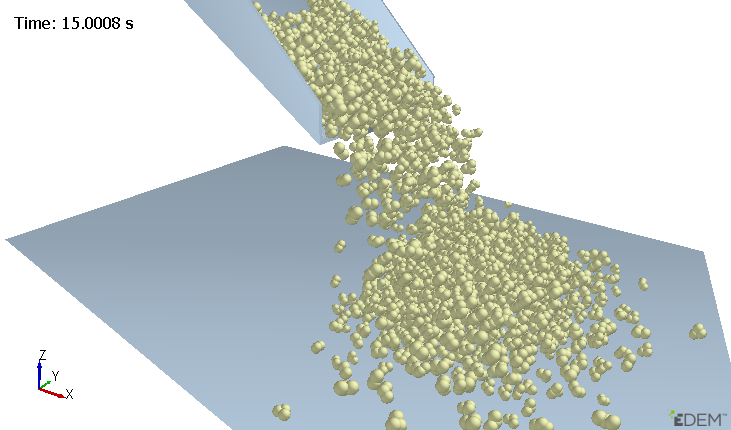 The following image shows an example where particles are not displayed and contacts are displayed:
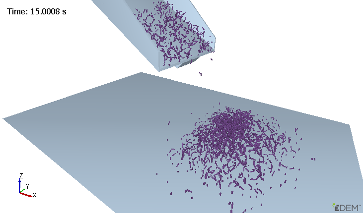
Display Attribute - Contact Vector
Displays an equal sized cylinder between all elements selected.
- Normal Force
Scales the contact vector by the magnitude of the contact normal force.
- Normal Overlap
Represents the contact as a flat plate between the elements.
- Tangential Force
Scales the contact by the magnitude of the contact tangential force.
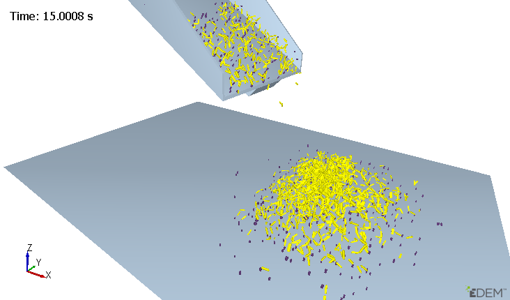
Opacity Changes the opacity of the contact display. Coloring Color By Indicates the color by which the contacts or contact groups will be visualized. Options are:- UniformThe contact group or groups will be visualized by the defined color. The following example shows Particle-particle contacts colored yellow and particle-geometry contacts colored purple:
Attribute
Colors any contact pair by a particular attribute. For more information about the available options, see the Color By Attribute Options table.
Color Select the element to color by and then select the attribute to color by. Smooth Colors Select the checkbox to smoothen the coloring of Geometry attributes for better visualization of the color gradation. Levels Select the desired number of coloring levels from the dropdown list to use in the attribute coloring analysis. Min Value Indicates the value of the selected attribute that will correspond with the color assigned for the minimum value in the legend. Auto Update Select the checkbox to allow EDEM to define the minimum values depending on the calculated results. Max Value Indicates the value of the selected attribute that will correspond with the color assigned for the maximum value in the legend. Auto Update Select the checkbox to allow EDEM to define the maximum values depending on the calculated results. Hide out of Bounds Select the checkbox to hide all the particles when Auto Update is not enabled, and if the value of the attribute colored is outside of the minimum and maximum range. Show Legend Select the checkbox to display the legends for all the selected elements. Position Legend Select the checkbox to position the legend by clicking anywhere in the Viewer. Legend Options Click to set the legend’s width, height, number of intervals, alignment, and title. Table 1. Color by Attribute Options Attribute Component Contact Normal (Polyhedral) Magnitude, X, Y, Z Contact Vector 1 Magnitude, X, Y, Z Contact Vector 2 Magnitude, X, Y, Z Normal Force Magnitude, X, Y, Z Normal Overlap N/A Overlap Volume (Polyhedral) N/A Penetration Depth (Polyhedral) N/A Tangential Force Magnitude, X, Y, Z Tangential Overlap N/A Custom Property Depends on the number of elements - Contact Vector