Display the Geometries Sub-section
The Geometries subsection allows you to modify and configure the display settings for all the Geometries in the simulation alternatively. You can visualize Cylindrical Periodic Boundary conditions in the Geometries subsection.
- Select the Display checkbox to enable or disable the display of the selected section or selection.
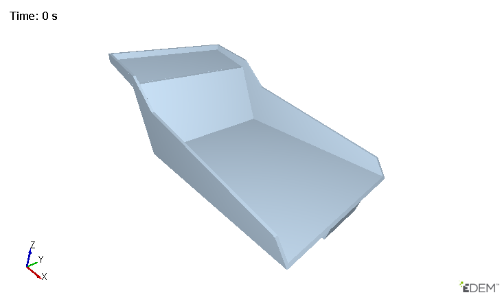
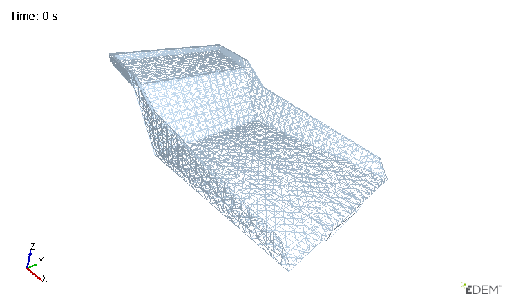
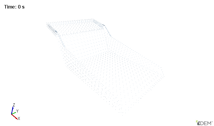
- Select the Display Mode. Options are: Filled, Mesh, or Point style display.
- Select Mesh to display the triangular elements the section is made up of.
- Select the Points to display the vertex of each element.
-
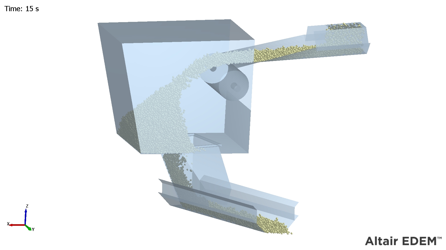
Opacity allows you to set the opacity level from 0 (fully transparent) to 1 (opaque).
Opacity of 1
Opacity of 0.75
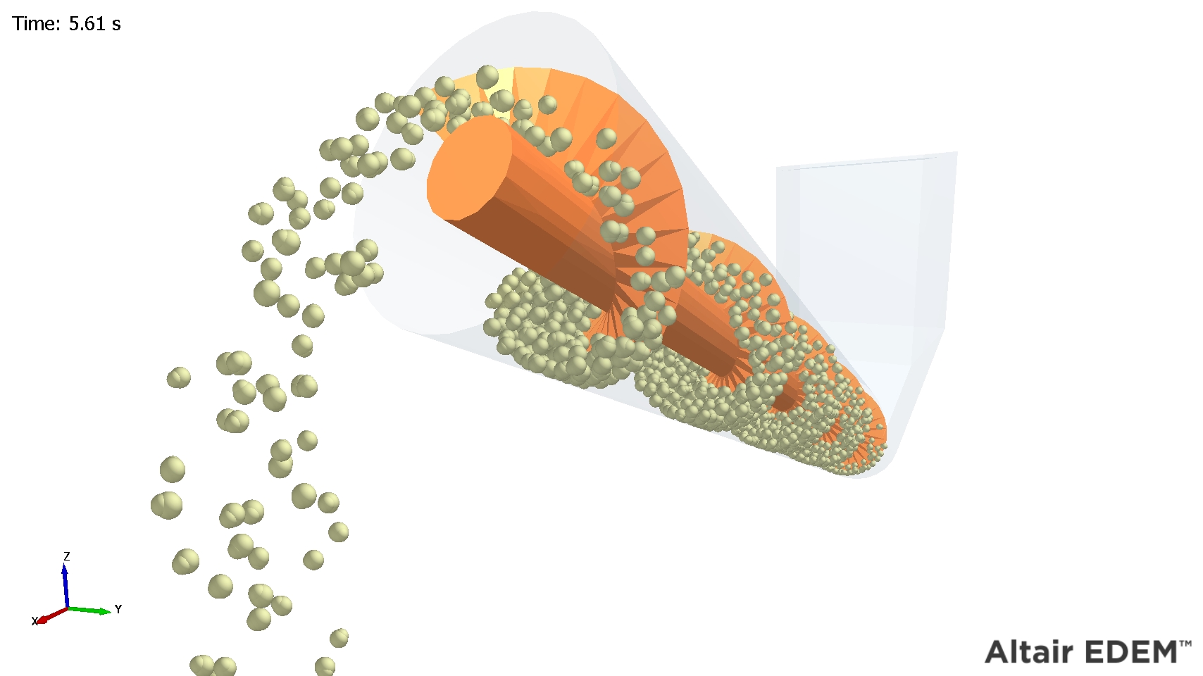
Opacity of 0.25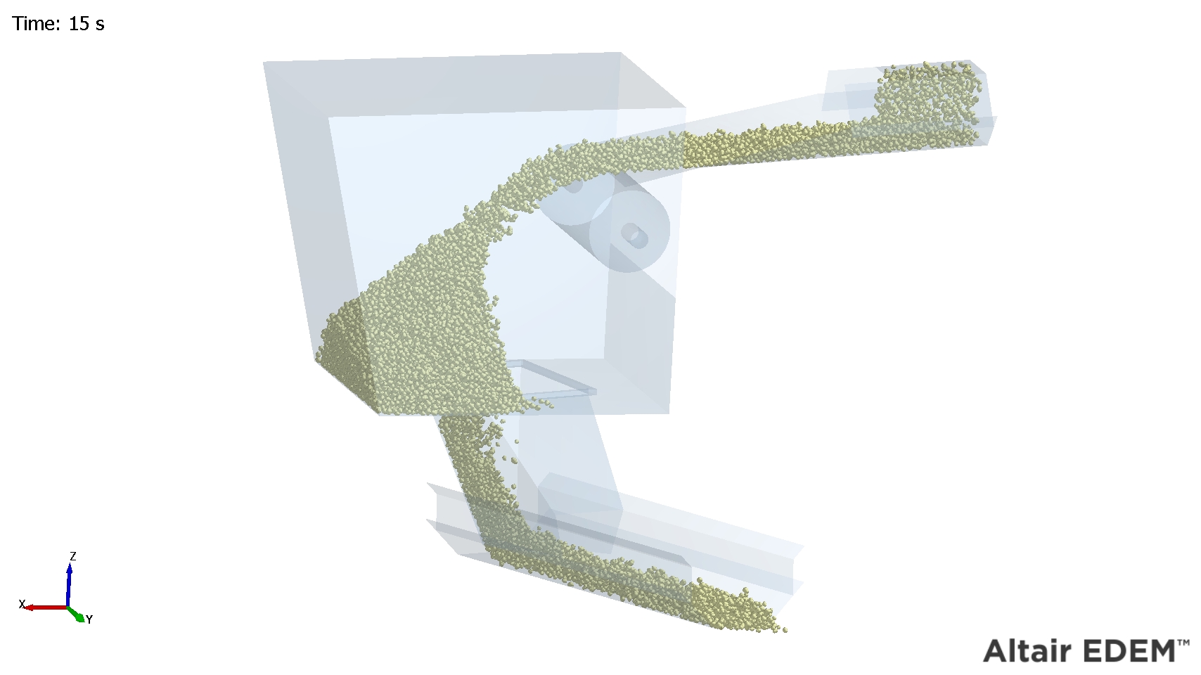
- Texture loads an image file (*.png, *.bmp or *.jpg) to use as a texture on Geometry surfaces.
- Color By Uniform colors the selected Geometry
or the Geometries will be colored as a whole by a single color.
- Color By - Attribute colors the Geometry by
attributes which are often unique to the Geometry element such as
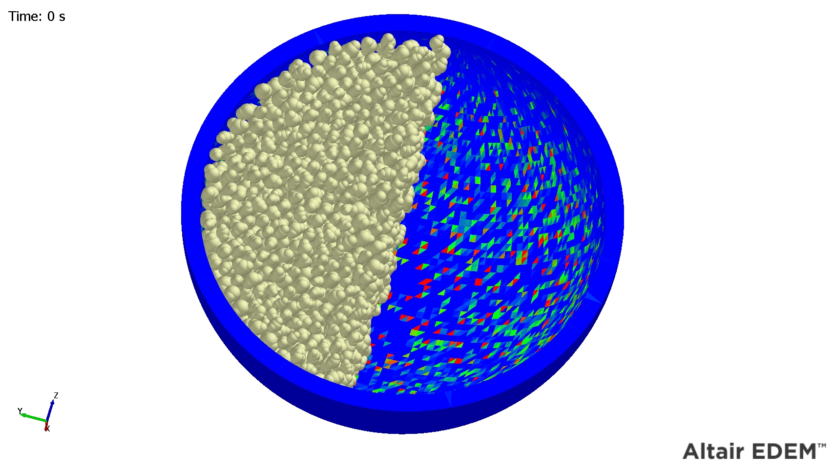
its ID or current force.Element attributes color the Geometry’s individual elements based on the value of that attribute. The element attributes are Compressive Force, ID, Pressure, Torque, Total Force, and Velocity. The torque selection is the Torque on the individual triangular Geometry element based around the position of the contact point relative to the element center point.
Element Attribute Components Geometry Center of Mass Magnitude, X, Y, Z Compressive Force N/A ID N/A Pressure N/A Torque (element) Magnitude, X, Y, Z Total force Magnitude, X, Y, Z Velocity Magnitude, X, Y, Z Velocity CoM Magnitude, X, Y, Z Custom Property Depends on the number of elements Area N/A When using element attributes to color a mesh the resolution of the coloring depends on the Geometries' mesh resolution.
The following Geometry has more mesh triangles, and the coloring is subsequently of a much higher resolution.
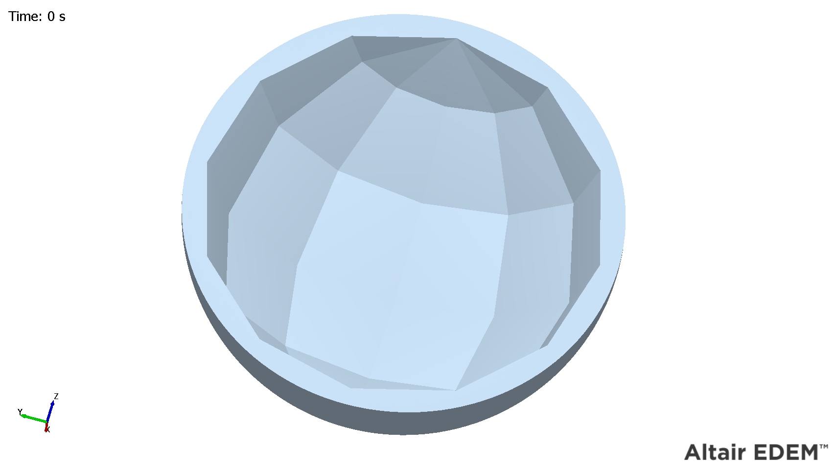
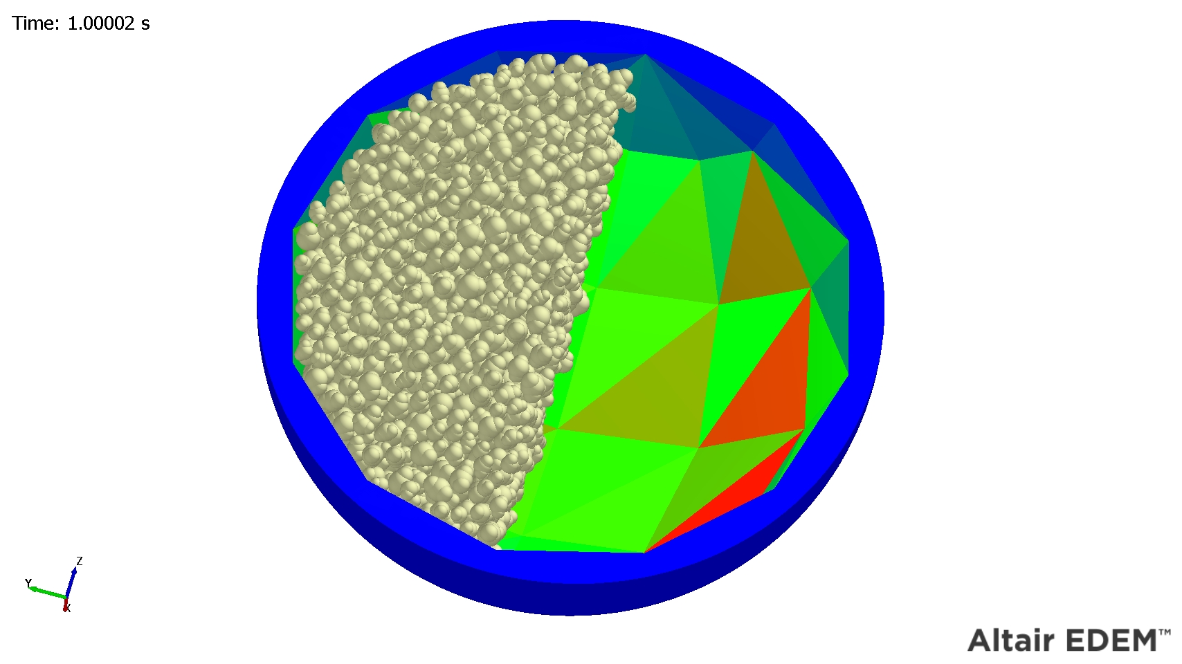 In the following Geometry shown as a large number of mesh triangles, the coloring can be shown per triangle.
Smooth Colors
You can smoothen the coloring of Geometry attributes for better visualization of the color gradation.
- Selecting Smooth Colors will blend the colors from the minimum value
to the maximum value smoothly without a distinct change in
color.
Selecting Smooth Colors on the faces interpolates the colors across each triangle based on the attribute at the nodes.
Select Multiple Geometries
You can select multiple Geometries by using Ctrl and clicking to select each Geometry.
- Select each Geometry.
- Select the Display Mode and Coloring for the selected group rather than modifying each Geometry individually.