X-Factor
Introduction
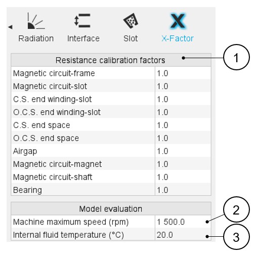
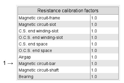
The X-Factor panel allows the user to define calibration factors to tune the thermal modeling on specific resistances.
The calibration factors set in this panel are considered in the results shown in Cooling subset, Internal panel environment, and the TEST environment.
The X-Factor panel also contains a set of parameters defining the internal cooling (coolants temperature and rotor speed), allowing the user to evaluate the thermal model embedded.
The effect on every X-Factor value can be directly seen in the outputs displayed in the internal cooling panel.
 |
|
|---|---|
| 1 | Table of the calibration factors allowing the user to tune the thermal modeling. Each X-factor tunes a set of resistances. The mapping showing the impact of each X-factor is explained in the below dedicated section. |
| 2 | Machine maximum speed. It is the maximum rotation speed for which the convection curves will be evaluated in the internal cooling datasheet. |
| 3 | Internal fluid temperature It is the temperature used in
the internal cooling panel to evaluate the convection and the
radiation occurring inside the machine. All the results shown in
the internal cooling panel use this temperature as the
temperature of the internal fluid enclosed in the machine. Most
of the curves shown in the internal cooling panel are plotted
for a range of temperatures going from this reference
temperature to 150 K above it. Note: This
temperature is only used for the model evaluation in the
internal cooling panel. This temperature does not affect the
test computations, where the internal fluid temperature is
found by the nonlinear solving during the solving of the
test. |
X-Factor mapping
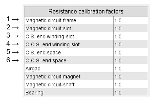
Each calibration factor impacts a specific set of resistances, among the most important thermal resistances of the thermal modeling of a machine.
 |
|
|---|---|
| 1 | Magnetic circuit-frame This calibration factor tunes the
total resistance between the stator yoke and the frame. This
total resistance is composed of two resistances in series:
|
| 2 | Magnetic circuit-slot This calibration factor tunes each
of the thermal resistances linking the stator core to the
winding. Each of these resistances consists of several
resistances in series:
|
| 3 | Connection Side end winding – slot This calibration factor tunes the conduction resistance between the slots (meaning In-slot winding) to the Connection Side end winding. |
| 4 | Opposite Connection Side end winding – slot.
This calibration factor tunes the conduction resistance between the slots (meaning In-slot winding) to the Opposite Connection Side end winding. |
| 5 | Connection Side end space This calibration tunes all the
resistances involved in thermal exchanges with or through the
Connection Side end space fluid:
The radiation resistances from the stator end, rotor end, and end winding to the frame and the end cap surfaces on the Connection Side. |
| 6 | Opposite Connection Side end space This X-factor tunes
every resistance involved in thermal exchanges with or through
the Opposite Connection Side end space fluid:
The radiation resistances from the stator end, rotor end, and end winding to the frame and the end cap surfaces on the Opposite Connection Side. |
 |
|
|---|---|
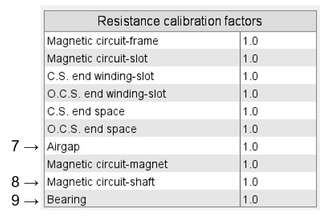
| 7 | Airgap This calibration factor tunes every resistance
involved in thermal exchanges with or through the airgap fluid:
The radiation from every rotor component having a border along the airgap to every stator component having a border along the airgap. |
| 8 | Magnetic circuit-shaft This calibration factor tunes the
total resistance between the rotor yoke and the shaft. This
total resistance is composed of two resistances in series:
|
| 9 | Bearings This calibration factor tunes the resistances existing across the Connection Side bearing and the Opposite Connection Side bearing. These resistances are the resistances computed directly from the bearing equivalent airgap thickness set by the user in Interface settings. |
 |
|
|---|---|
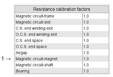
| 1 | Magnetic circuit-magnet (only for SMPM machines) For
every existing magnet, this calibration factor tunes the total
resistance existing between this magnet and every component of
the rotor magnetic circuit around it. Each of these resistances
is composed of three resistances:
|
 |
|
|---|---|
| 1 | Magnetic circuit-bar For every existing bar, this
calibration factor tunes the total resistance existing between
this bar and every component of the rotor magnetic circuit
around it. Each of these resistances is composed of three
resistances:
|
 |
|
|---|---|
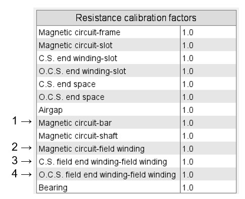
| 1 | Magnetic circuit-bar For every existing bar, this
calibration factor tunes the total resistance existing between
this bar and every component of the rotor magnetic circuit
around it. Each of these resistances is composed of three
resistances:
|
| 2 | Magnetic circuit-field winding This calibration factor
tunes each of the thermal resistances linking the rotor core to
the field winding. Each of these resistances consists of several
resistances in series:
The conduction through the coil (using the equivalent conductivity defined in the settings “Field winding model” of the “Internal cooling” panel). |
| 3 | Connection Side field end winding – field winding This calibration factor tunes the conduction resistance between the field winding (meaning In-coil winding) and the Connection Side end winding. |
| 4 | Opposite Connection Side field end winding – field
winding This calibration factor tunes the conduction resistance between the field winding (meaning In-coil winding) and the Opposite Connection Side end winding. |