Fluidic
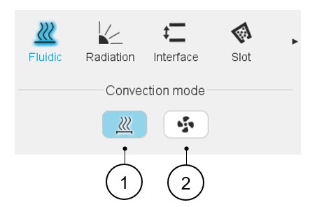
Convection mode
The tools available in the fluidic tab allow defining the parameters that drive the convection phenomenon in the end spaces, involving the surfaces of the frame (internal surface), the end cap (internal surface), the shaft, the rotor and stator ends, and the end winding or potting.
Two choices are available to define the convection occurring on the external surface of the frame and of the end caps: Natural or Forced.
 |
|
|---|---|
| 1 | Natural convection |
| 2 | Forced convection |
Natural convection
- The differences of fluid temperature existing in different volumes of the end spaces (giving a difference of fluid density) create some natural fluid swirling in the end spaces.
- The fluid movement is induced by the rotation speed of the machine.
Our internal natural convection model is based on classical correlations for end spaces, considering different fluid velocities for the parts close to the rotating parts and far from the rotating parts.
Forced convection.
This convection mode allows forcing the convection model to be used for every region of the end spaces.
- Increased convection effects due to rotor fins of shaft mounted internal fans.
- A fan internally forcing constant ventilation whatever the rotation speed of the machine.
- Some forced convection coefficients in the end spaces.
 |
|
|---|---|
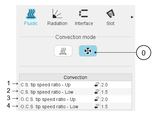
| 0 | The forced convection mode is selected. |
| 1-4 | Forced convection: The end spaces are divided into four areas, corresponding to four inputs the user must define in forced convection mode. |
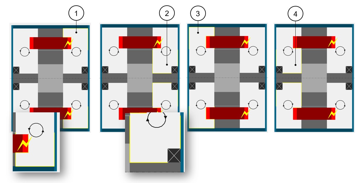
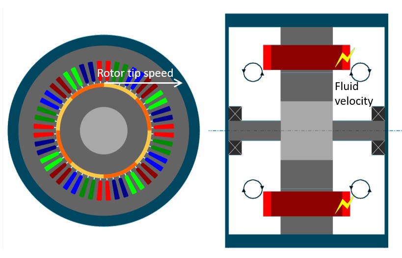
When selecting one of these four inputs, the corresponding exchange areas are highlighted in the axial view of the machine. See the illustrations below.
 |
|
|---|---|
| 1 | The « Upper » Connection Side region, corresponding to the Connection Side convection areas far from the rotating parts. |
| 2 | The « Lower » Connection Side region, corresponding to the Connection Side convection areas close to the rotating parts. |
| 3 | The « Upper » Opposite Connection Side region, corresponding to the Opposite Connection Side convection areas far from the rotating parts. |
| 4 | The « Lower » Opposite Connection Side region, corresponding to the Opposite Connection Side convection areas close to the rotating parts. |
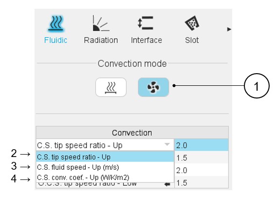
- A tip speed ratio
- A fluid speed
- A convection coefficient
The user can select the input mode of each region using the dedicated arrow or clicking on the input mode to change it.
 |
|
|---|---|
| 1 | The forced convection mode is selected. |
| 2 | Definition of the ratio between the rotor tip speed and the internal fluid velocity on the connection side, far from the rotor. See additional information below. |
| 3 | Definition of the fluid constant speed on the connection side,
far from the rotor. The « Constant fluid speed » input mode can be used to model a constant ventilation speed. |
| 4 | Definition of the convection coefficient at reference internal
fluid. The « Convection coefficient » input mode allows directly forcing a convection coefficient in the corresponding region. |
Information about the « Tip speed ratio » input mode
The « Tip speed ratio » input mode allows setting a fluid velocity proportional to the rotor tip speed. This factor works as a divider, e.g., a tip speed ratio of 2 means that the fluid in this section is moving at half the speed relative to the rotor’s tip speed.
This can be used to model a shaft mounted fan of rotor fins.
The default values of tip speed ratios are 2 for the regions far from the rotor.
A tip speed ratio of 2 for an « Upper » region (meaning a region far from the rotor) corresponds to a shaft mounted fan, or rotor fins, that blows air to this region with an average efficiency.
For the « Upper » region of a side without a fan or fins, it is advised to set a rotor tip speed ratio of 5. This corresponds to theFluxMotor natural convection model.
The default value of tip speed ratio is 1.5 for regions close to the rotor.