Interface
Interface mode
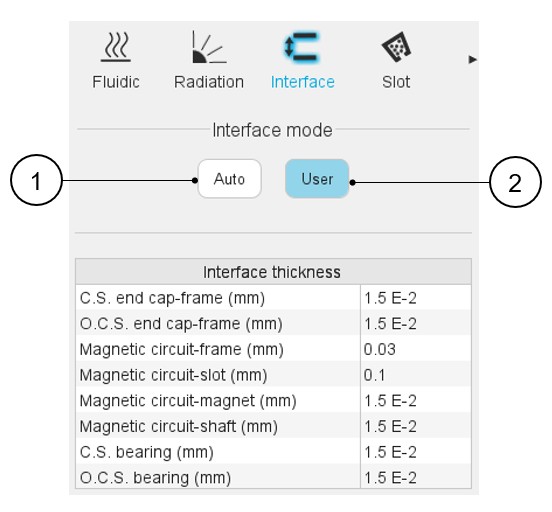
This panel allows describing imperfect contact between the different components of the machine.
The imperfect contacts are here modeled as a parasitic airgap between two parts, through which the heat must be conducted to go from one part to the other.
The interface gaps are composed of air at the atmospheric pressure, at 20 °C, equivalent to 293.15K. For more information on material properties, please refer to our material database (“Materials application”).
Two ways are proposed to define the interface: an automatic and a user one.
 |
|
|---|---|
| 1 | Auto mode: This mode allows us to set the interface thicknesses automatically by internal process. |
| 2 | User mode: This mode allows us to set the interface thicknesses manually. |
User mode
- Each interface/mounting of a laminated part on a solid material
- Between the magnetic circuit and the frame
- Between the magnetic circuit and the magnets (only present in SMPM machines)
- Between the magnetic circuit and the ring bars (only present in IMSQ machines)
- Between the magnetic circuit and the shaft
- The imperfect contact between the magnetic circuit and the liner surrounding the slot.
- The imperfect contact between the frame (straight part) and the two end caps.
- The bearings: An interface gap thickness is used to compute the thermal
resistance of each bearing. These values of contact thickness are used in
computations for both bearings (Connection Side and Opposite Connection
Side).
In the user mode, the following thicknesses must be set:
- CS end cap-frame interface thickness, with a default value of 15 micrometers.
- OCS end cap-frame interface thickness, with a default value of 15 micrometers.
- Magnetic circuit – frame interface thickness, with a default value of 30 micrometers.
- Magnetic circuit – slot interface thickness, with a default value of 100
micrometers.
This corresponds to the imperfect contact between the liner and the iron core.
- Magnetic circuit – magnet interface thickness (only for SMPM machines), with a default value of 15 micrometers.
- Magnetic circuit – bar interface thickness (only for IMSQ machines), with a default value of 15 micrometers.
- Magnetic circuit – shaft interface thickness, with a default value of 15 micrometers.
- CS Bearings equivalent interface thickness, with a default value of 15
micrometers.
OCS Bearings equivalent interface thickness, with a default value of 15 micrometers.