Thermal diagram
Introduction
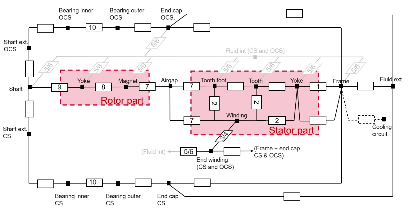
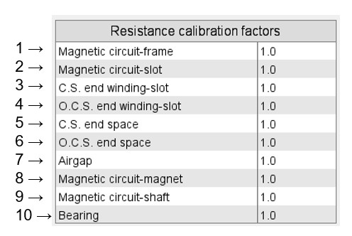
Synchronous machines with permanent magnets
The following picture gives an example of a simple thermal circuit, including the main resistances corresponding to the default synchronous machine with permanent magnets.
 |
|---|
 |
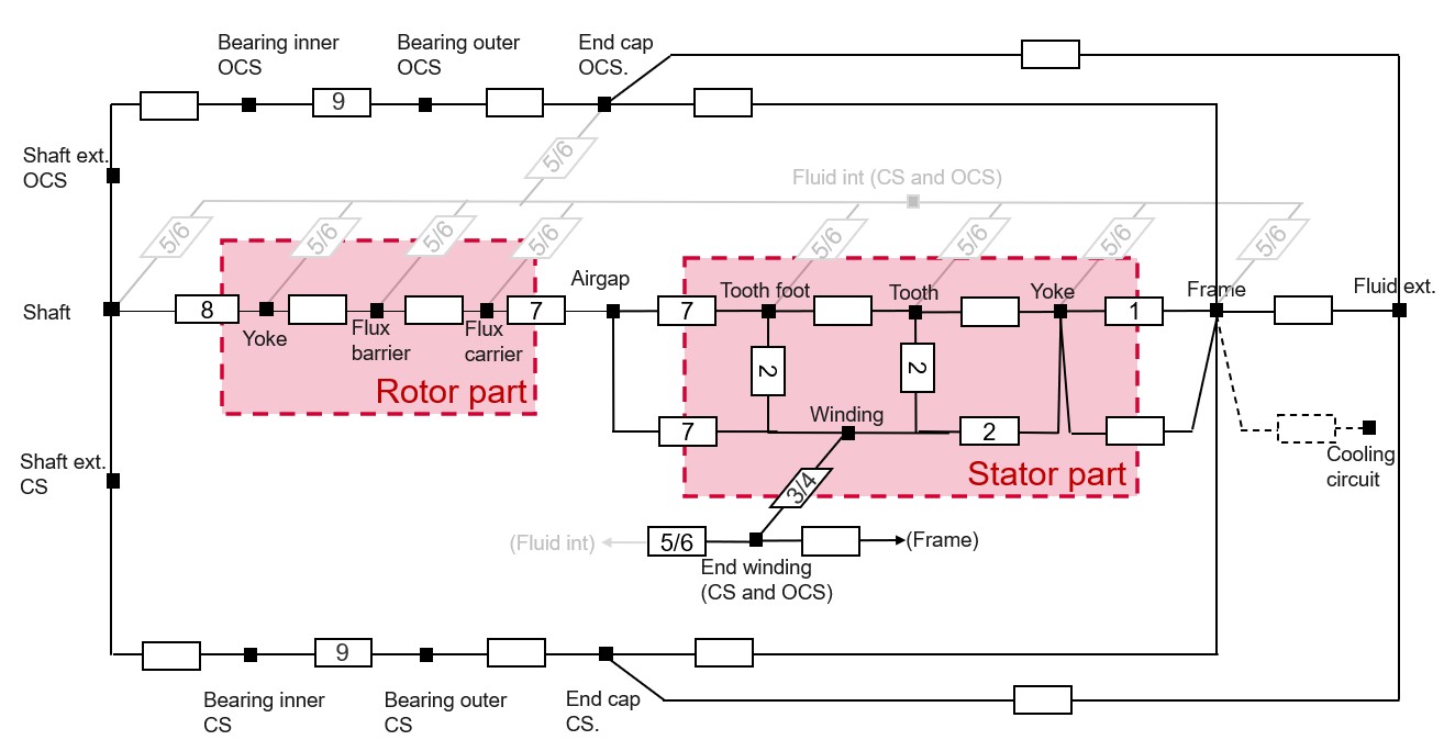
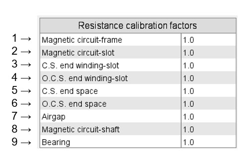
Reluctance synchronous machines
The following picture gives an example of a simple thermal circuit, including the main resistances corresponding to the default reluctance synchronous machine.
 |
|---|
 |
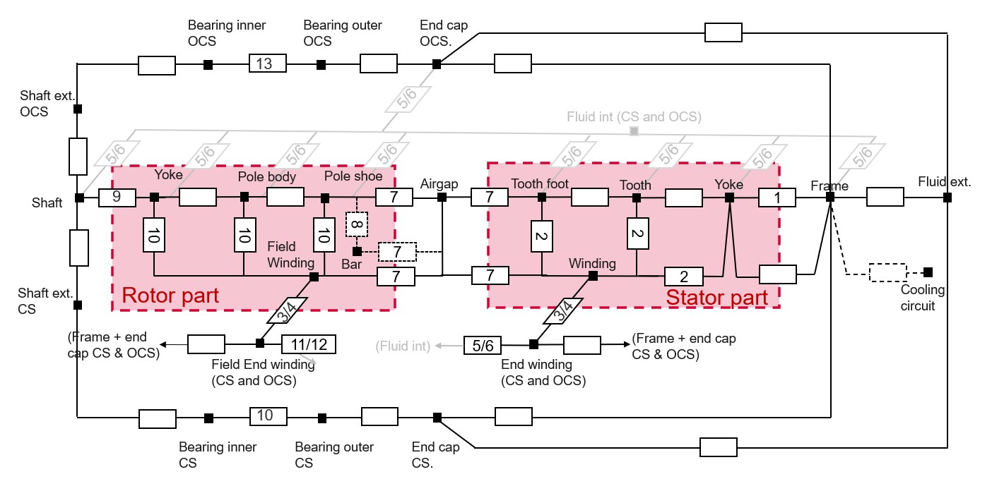
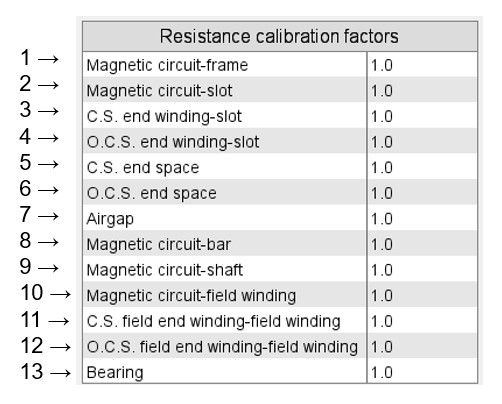
Wound field synchronous machines – Inner salient poles
The following picture gives an example of a simple thermal circuit, including the main resistances corresponding to the default wound field synchronous machine with inner salient poles.
 |
|---|
 |
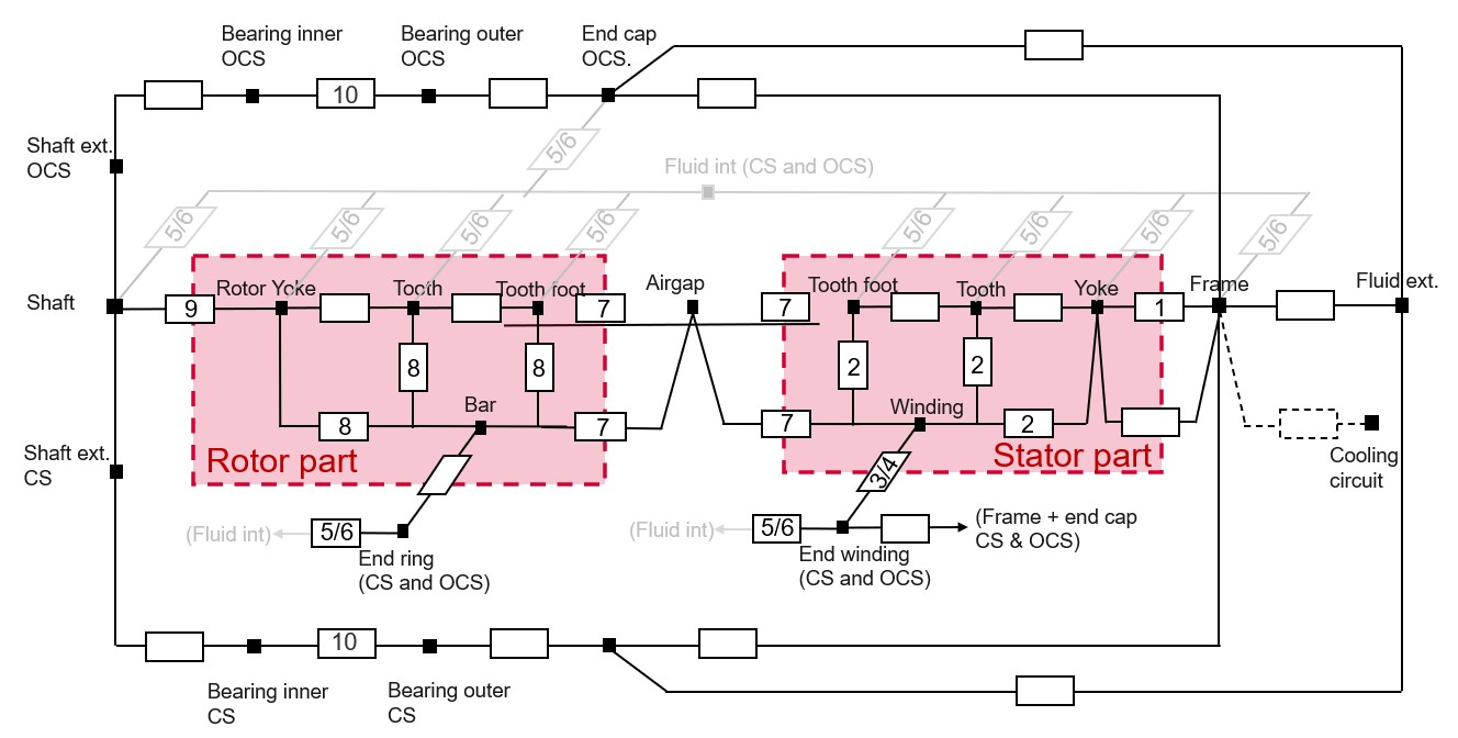
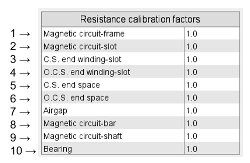
Induction machine with squirrel cage
The following picture gives an example of a simple thermal circuit, including the main resistances corresponding to the default induction machine with a squirrel cage.
 |
|---|
 |