Damper
Illustration
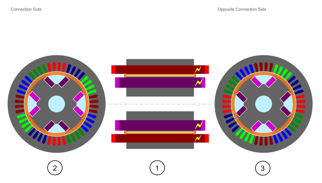
The rotor of a wound field synchronous machine is very often composed of a magnetic circuit with a damper included inside.
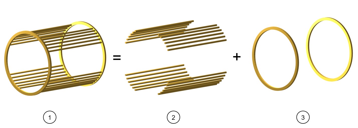
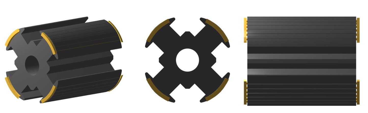
The damper is designed with bars that are short-circuited by end-ring on both sides - Connection Side (C.S.) and Opposite Connection Side (O.C.S.). The end-rings can be designed with full rings or with sectors on each pole.
Bars - General information
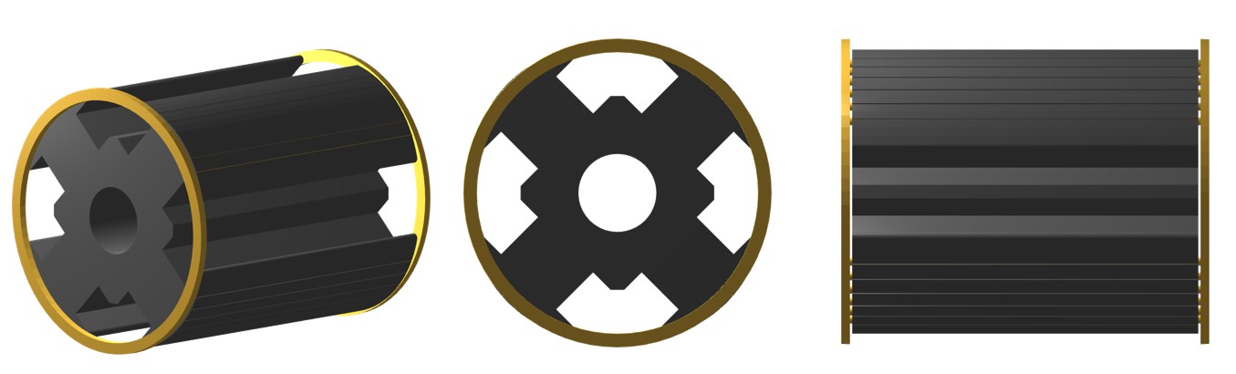
When needed, the design of the damper bars (number, position and dimensions) is done in the part Pole (Pole shoe) and they can be parameterized as well.
It is why there is not a dedicated area in the Motor Factory design area to change the shape of bars only. To change the number and the shape of bars, one must change the whole pole topology (Pole shape in the Motor Factory – design area).
Overview
The type of end-ring can also be defined as a full ring or end-ring sectors.
A section scrolling bar allows choosing the section in which user inputs are defined.
Scrolling selection bar where Design, Impedance, X-Factor and Operating conditions sections can be selected.
 |
|
|---|---|
| 1 | Selection of the Damper panel (Click on the Damper
icon) Several sections allow defining all characteristics that deal with the end-ring: Design, Impedance, X-Factor and Operating. |
| 2 | Access to the section dedicated to the design of the
end-rings. Note: By default, the section
Design is selected. |
| 2.1 | The type of end-ring can be defined as a full ring or end-ring sectors. |
| 2.2 | User inputs dedicated to the design of the slot. |
| 3 | Impedance tab gives the tools to compute the inter-bar impedance of the squirrel cage. |
| 4 | X-Factor tab gives access to the user coefficients (calibration factors = X-factors) that allows to tune the inter-bar end-ring resistances and inductances. |
| 5 | Operating tab to define a working point for evaluating the characteristics of the inter-bar end-ring impedances. |