Operating
Overview
The inter-bar end-ring impedances must be defined for a working point.
A table allows the user to describe a working point, defined by a frequency and a
slip (or by the machine’s rotating speed).
Note: For constant
computation mode, the inter-bar impedances do not depend on the frequency, nor
on the slip (or speed). Therefore, the working point evaluation will give the
same results in this mode for any frequency and slip.
 |
|
|---|---|
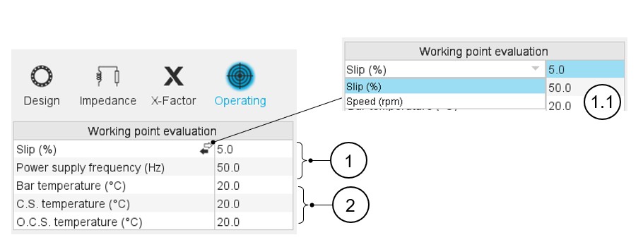
| 1 | Definition of the working point characteristics for which the impedances will be evaluated (Slip or speed and power supply frequency). |
| 1.1 | Either the slip or the speed must be defined. |
| 2 | Definition of the temperatures (Bars and end-rings) for which the impedances will be evaluated. |
Note:
- The main results data are given in the datasheet (central window of the
end-ring area).
- Material, Masses and cost
- Material electrical resistivity
- Inter-bar resistance and inductance
- In the table “Material electrical resistivity data”, the “corrected” resistivities are computed to give a bar resistance on the rotor lamination length equal to the bar resistance computed on the total bar length with the bar real resistivity (rotor lamination length + bar extensions). The corrected electrical resistivity values are used in Flux® 2D for internal computations and exports.
- Inter-bar impedance curve at reference temperature is plotted: The end-ring impedances in the range of possible slips, and the impedances at the working point defined in the input table “Working point evaluation” are plotted as well.