Operating
Overview
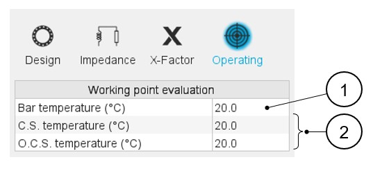
The inter-bar end-ring impedances must be defined by considering referent temperatures for the bars and end-rings.
 |
|
|---|---|
| 1 | Definition of the temperatures (Bars) for which the impedances
will be evaluated. Note: This value impacts
the bar extension impedance to be considered with the end-ring
one. |
| 2 | Definition of the temperatures at each side (end-rings) for which the impedance will be evaluated. |
Note:
- The main results data are given in the datasheet (central window of the
end-ring area).
- Material, Masses and cost
- Material electrical resistivity
- Inter-bar resistance and inductance
- In the table “Material electrical resistivity data”, the “corrected” resistivities are computed to give a bar resistance on the rotor lamination length equal to the bar resistance computed on the total bar length with the bar real resistivity (rotor lamination length + bar extensions). The corrected electrical resistivity values are used in Flux® 2D for internal computations and exports.