Field winding
Field winding conduction mode
The field windings are located on the rotor part of the wound field synchronous machines. The thermal exchanges from the conductors of the field winding to the rotor core are complex phenomena for which FluxMotor embeds a dedicated model.
This panel allows choosing the conduction model, from the conductors to the rotor core.
By default, a FluxMotor model is proposed. This model uses the
field winding fill factor, the conductor shape, and the conductivities of the
materials inside the field winding to compute two equivalent conductivities:
- The radial and orthoradial conductivity of the winding, used to compute thermal exchanges from the winding to the rotor core.
- The axial conductivity of the winding used to compute thermal exchanges from the field winding (straight part) to the end windings.
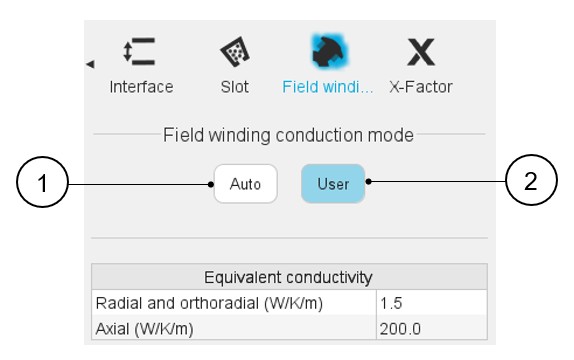
Two ways are proposed to define the field winding conduction: an automatic and a user one.
 |
|
|---|---|
| 1 | Auto mode: This mode allows us to set the field winding conduction automatically by internal process |
| 2 | User mode: This mode allows us to set the Field winding conduction manually |
User mode
The user mode allows to set the user field winding conductivities manually.
In user mode, the following inputs must be set:
- The radial and orthoradial conductivity of the winding, used to compute
thermal exchanges from the winding to the rotor core.
The default value is 1.5 W/(K.m).
- The axial conductivity of the winding used to compute thermal exchanges from the field winding (straight part) to the end windings. The default value is 200 W/(K.m).