SS-V: 1020 Curved Beam
Test No. VS03 Find tip deflections of a curved beam when subjected to in-plane and out-of-plane loads.
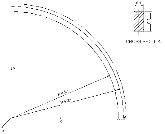
Definition
A curved beam, spanning a 90 degree arc is fixed at one end and free at the other (Figure 1). The beam is subjected to
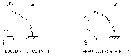
two different loads at the free end (Figure 2):
- in-plane load
- out-of-plane load
The units are IPS.
The material properties are:
- Properties
- Value
- Modulus of Elasticity
- 1e+7 psi
- Poisson's Ratio
- 0.25
Results
The following table summarizes tip displacement (center face) in the direction of the load
[in].
| Theory (Curved beam theory) | SimSolid | % Difference | |
|---|---|---|---|
| In-plane Load (+Y direction) | 8.7340E-02 | 8.8554E-02 | 1.39% |
| Out-of-plane Load (+ Z direction) | 5.0220E-01 | 5.0542E-01 | 0.64% |
1 MacNeal, R.H., and
Harder, R.L., A Proposed Standard Set of Problems to Test Finite Element
Accuracy, Finite Elements in Analysis and Design, 1 (1985)
3-20.