SS-V: 1000 Straight Cantilever Beam
Test No. VS01 Find tip deflections of a cantilever beam when subjected to extension, shear, and twisting loads.
Definition
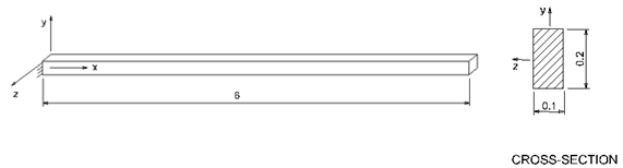
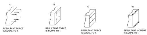
A straight cantilever beam (Figure 1) is subjected to four different loads at the free end (Figure 2).
- extension
- in-plane shear
- out of plane shear
- twisting
The units are IPS.
Loads are uniformly distributed along the face of the beam or along edges.
The material properties are:
- Properties
- Value
- Modulus of Elasticity
- 1e+7 psi
- Poisson's Ratio
- 0.3
Results
The following table summarizes the tip displacements [in].
| Theory (beam theory) | SimSolid | % Difference | |
|---|---|---|---|
| Axial Loading (+X direction) | 3.0000E-05 | 3.0043E-05 | 0.14% |
| In-plane Shear (+Y direction) | 1.0810E-01 | 1.0823E-01 | 0.12% |
| Out-of-plane Shear (+Z direction) | 4.3210E-01 | 4.3244E-01 | 0.08% |
| Twisting* (+Z direction) | 3.4060E-03 | 3.4558E-03 | 1.46% |
*Twist load was 1 in-lbf X-moment applied as remote load at end face of the beam.
1 MacNeal, R.H., and
Harder, R.L., A Proposed Standard Set of Problems to Test Finite Element
Accuracy, Finite Elements in Analysis and Design, 1 (1985)
3-20.