Part 1: Export the Superelement
Import Geometry
- Open a new SimSolid session.
-
Click
 Import from file .
- In the Open geometry files dialog, choose Superelement_export.step.
-
Click Open.
The assembly will load in the modeling window.
Assign Material
- In the Project Tree, open the Assembly workbench.
-
In the Assembly workbench, select
 Apply/review
materials > Apply materials.
Apply/review
materials > Apply materials.
- Select Steel from the Generic materials list.
- Click Apply to all parts.
- Click Close.
Create Modal Superelement Export Analysis
- On the main window toolbar, click Modal Analysis > Modal Superelement Export.
- For Number of modes, enter 12.
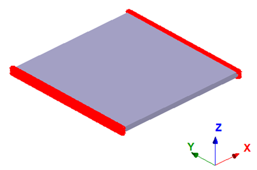
Create Immovable Constraint
-
In the Analysis Workbench, select
 Constraints > Immovable support.
- In the dialog, verify the Faces radio button is selected.
-
In the modeling window, select the face(s) highlighted in
orange in the figure below.
Figure 1. 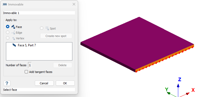
-
Click
OK.
The new constraint, Immovable 1, appears in the Project Tree.
Import Superelement Interface Points
-
On the Analysis Workbench, click
 Interface points.
- Click Import from .csv.
-
Select the Interface_points.csv file from the File
Explorer.
Interface points coinciding at the same coordinate points or with same ID will show warnings.
- Optional:
Edit the coordinate units.
By default, SimSolid accounts the units from the imported geometry.
-
Click OK.
Point set 1 will be mapped to the respective location of the model.
Edit Solution Settings
- In the Analysis branch of the Project Tree, double-click on Solution settings.
- In the Solution settings dialog, for Adaptation select Global+Local in the drop-down menu.
- Click OK.
Run Analysis
- In the Project Tree, open the Analysis Workbench.
-
Click
 Solve.
Export Superelements
After solving the modal superelement export analysis, Export is enabled in the Analysis Workbench.
-
Click
 Export to create the DMIG file.
- In the dialog, enter units for Coordinates as [mm], Stiffness matrix as [N/mm], and Mass matrix as [t].
- Click OK.
-
Browse to the desired location in File Explorer and click
Save.
The DMIG file is created.