SS-T: 4210 Rotordynamic Analysis
Tutorial Level: Advanced Create modal rotordynamics analysis in SimSolid for a vertical wind turbine assembly.
- Purpose
- SimSolid performs meshless
structural analysis that works on full featured parts and assemblies, is
tolerant of geometric imperfections, and runs in seconds to minutes. In this
tutorial, you will do the following:
- Learn to create a modal rotordynamics analysis
- Model Description
- The following model file is needed for this tutorial:
- rotordynamics.ssp
-
Figure 1. 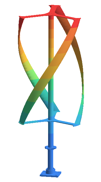
This file has the following specifications:- Material is set to Steel for all parts.
- Regular connections - 3 mm gap and penetration tolerance.
- SimSolid automatically creates bonded contact conditions.
Open Project
- Start a new SimSolid session.
-
In the main window toolbar, click Open Project
 .
.
- In the Open project file dialog, choose rotordynamics.ssp
- Click OK.
Create Rotordynamics Analysis
-
In the main menu toolbar,
select
 Modal >
  Modal
rotordynamics.
Modal
rotordynamics.
- In the setup dialog, select the Coriolis effect checkbox.
- Specify the number of modes as 9.
-
Click
OK.
The new modal rotor dynamics analysis appears in the Project Tree.
Apply Rotational Inertia Loads
-
In the Analysis Workbench toolbar, select
 Rotational inertia load.
- In the dialog, verify the Select a cylinder radio button is selected.
-
In the modeling window, select the face(s) highlighted in
orange in the figure below.
Figure 2. 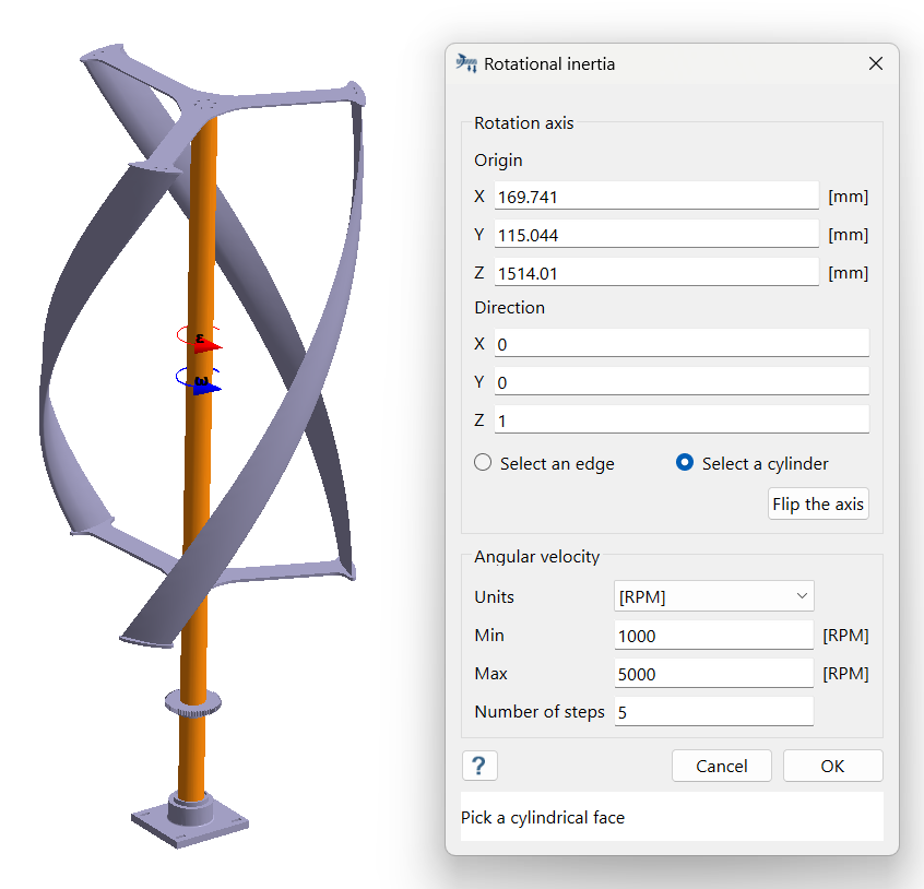
- For the Direction, enter (0,0,1) for X, Y, and Z.
- For Angular velocity, change the units to RPM, enter 1000 for Min, 5000 for Max, and 5 for Number of steps.
- Click OK.
Create Immovable Support
-
In the Analysis Workbench, select
 Constraints > Immovable support.
- In the dialog, verify the Faces radio button is selected.
-
In the modeling window, select the face(s) highlighted in
orange in the figure below.
Figure 3. 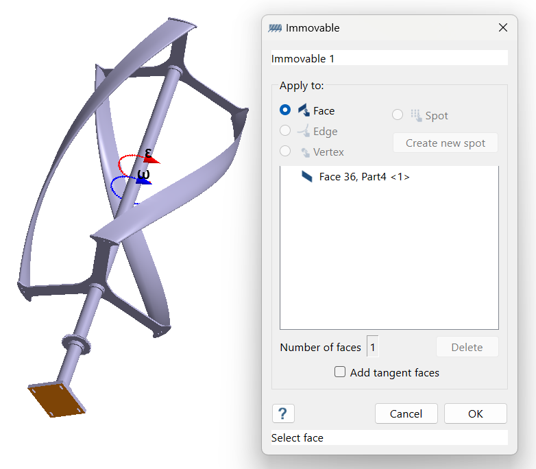
-
Click
OK.
The new constraint, Immovable 1, appears in the Project Tree. A visual representation of the constraint is shown on the model.
Edit Solution Settings
- In the Analysis branch of the Project Tree, double-click on Solution settings.
- In the Solution settings dialog, for Adaptation select Global+Local in the drop-down menu.
- Click OK.
Run Analysis
- In the Project Tree, open the Analysis Workbench.
-
Click
 Solve.
Review Modes
-
In the Analysis Workbench, click
 Result
plot > Displacement > Displacement magnitude.
The Legend window opens and displays the contour plot. The Modes window opens and displays a list of modes.
Result
plot > Displacement > Displacement magnitude.
The Legend window opens and displays the contour plot. The Modes window opens and displays a list of modes.Figure 4. 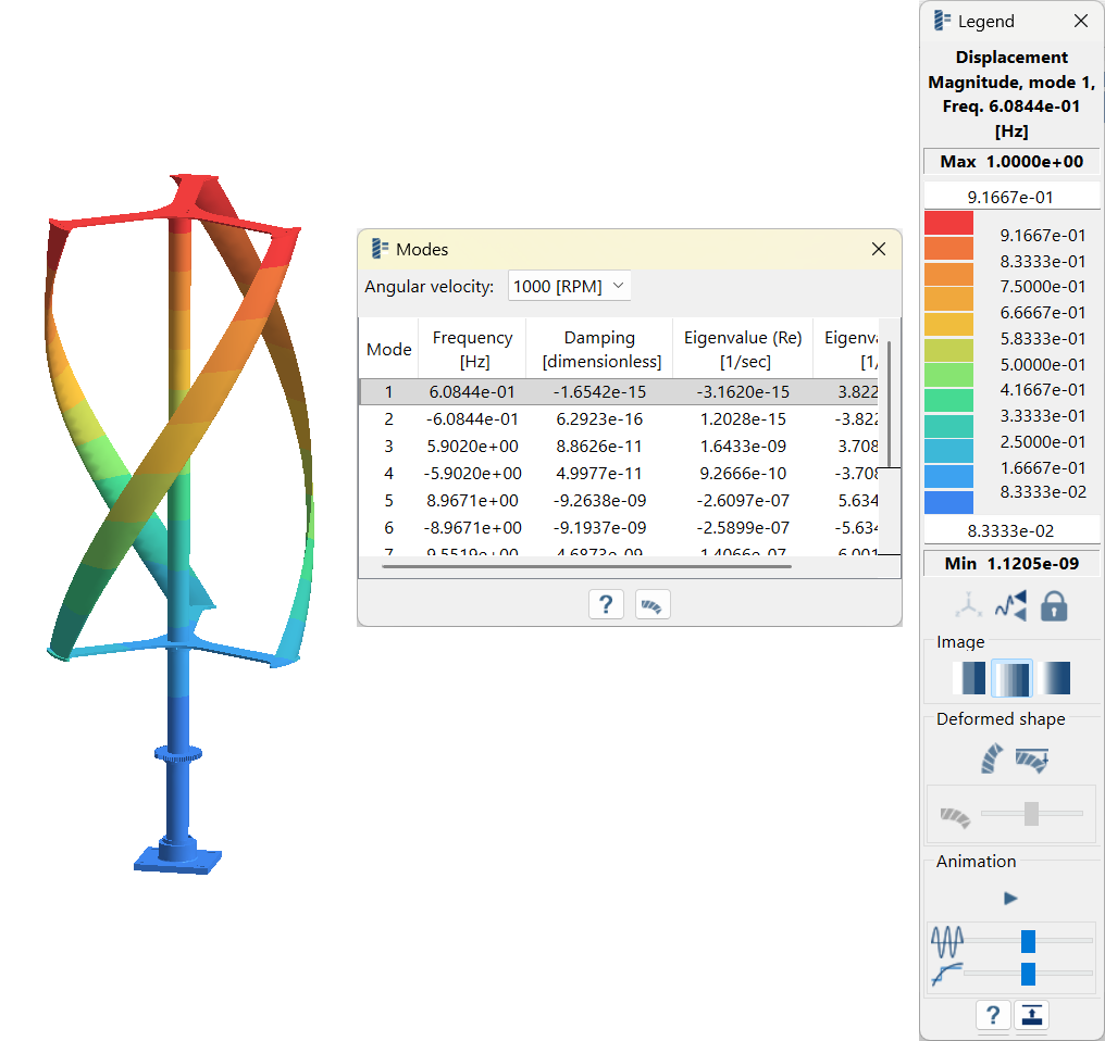
-
Review the modes.
-
In the Legend window, click
 Start/stop
animation to view the mode animation.
Start/stop
animation to view the mode animation.
Figure 5. Mode 1 
-
In the Legend window, click
- Optional:
Different angular velocities can be cycled by selecting from the
Angular velocity dropdown.
Tip: The units for angular velocity can be changed by double-clicking on Units in the Project Tree.
Plot Campbell Diagram
-
In the Analysis Workbench, click
 Diagrams > Campbell diagram.
Campbell diagram plots the natural frequencies to the rotor against its operating speeds which is used to find the critical speeds of the rotating system. Positive modes are plotted.
Diagrams > Campbell diagram.
Campbell diagram plots the natural frequencies to the rotor against its operating speeds which is used to find the critical speeds of the rotating system. Positive modes are plotted. - Under Angular velocity multipliers, enter 0.001 for Multiplier.
-
Click Add to add the line on the plot.
The points at which the line intersects the natural frequencies line are known as the critical speeds.
Figure 6. 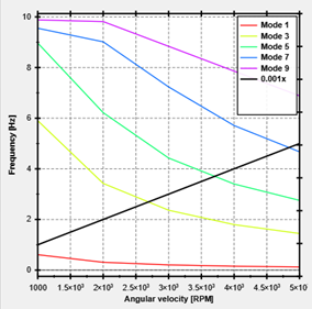
- Optional: Plot the Damping diagram which shows how the damping is changed with respect to angular velocity.