SS-T: 4200 Electromagnetic Analysis
Tutorial Level: Advanced Create S-parameters and modal electromagnetics analysis in SimSolid for a t-block model. A waveguide t-block is a 3-port device used to divide or combine power in waveguide system. For this tutorial, we are using an H-plane waveguide system.
- Purpose
- SimSolid performs meshless
structural analysis that works on full featured parts and assemblies, is
tolerant of geometric imperfections, and runs in seconds to minutes. In this
tutorial, you will do the following:
- Learn to create an electromagnetic analysis
- Model Description
- The following model file is needed for this tutorial:
- electromagnetics.ssp
-
Figure 1. T-block model 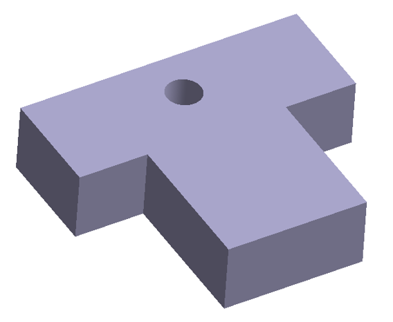
Open Project
- Start a new SimSolid session.
-
In the main window toolbar, click Open Project
 .
.
- In the Open project file dialog, choose electromagnetics.ssp
- Click OK.
Define Medium Material
- In the menu bar, click .
- In the dialog, right-click on the Generic materials folder, and then select Add Material from the context menu.
- Edit the material name to Air.
- For Density, enter 1000 kg/m3.
-
Enter the electromagnetic material properties.
- Enter Relative permittivity as 1.
- Enter Relative permeability as 1.
- Click Apply.
- Click Save.
Assign Material
- In the Project Tree, open the Assembly workbench.
-
In the Assembly workbench, select
 Apply/review
materials > Apply materials.
Apply/review
materials > Apply materials.
- Select Air from the Generic materials list.
- Click Apply to all parts.
- Click Close.
Create S-Parameter Analysis
-
In the main menu toolbar,
select
 Electromagnetics >
  S-parameters.
- In the setup dialog enter Lower limit, [Hz] as 14e9 and Upper limit, [Hz] as 16e9.
-
Specify the number of frequencies as 3.
This will create a frequency span starting from 14GHz to 16GHz with increment of 1GHz.
-
Click
OK.
The new S-parameter analysis will appear in the Project Tree.
Define Waveguide Ports
- In the Project Tree, select the S-parameters subcase to open the Analysis Workbench.
-
In the Analysis Workbench, select
 Waveguide
port.
Waveguide
port.
-
In the Waveguide port dialog, select the face shown in the
figure below and keep the power value as 1W.
Figure 2. 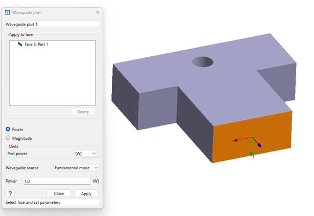
- Click Apply.
-
Repeat steps 2-4 for the other two faces on the two sides.
Note: Only selection of one flat rectangular face per waveguide port is allowed.
Figure 3. 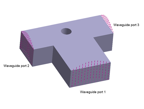
Create Perfect Electric Conductor (PEC)
-
In the Analysis Workbench, select
 Perfect
electrical conductor.
Perfect
electrical conductor.
-
In the Perfect Electrical Conductor dialog, select the
remaining faces to which waveguide ports were not applied.
Tip: Hold control on keyboard and drag select the entire model, SimSolid will automatically skips the faces to which waveguides ports were applied.
Figure 4. 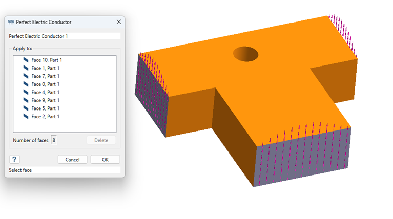
- Click OK.
Edit Solution Settings
- In the Analysis branch of the Project Tree, double-click on Solution settings.
- In the Solution settings dialog, for Adaptation, select Global in the drop-down menu.
- Click OK.
Run Analysis
- In the Project Tree, open the Analysis Workbench.
-
Click
 Solve.
Note: When using Global solution settings, this analysis can take up to ten minutes to run.
Solve.
Note: When using Global solution settings, this analysis can take up to ten minutes to run.
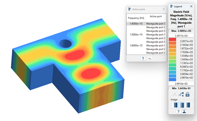
Review Results
In the Analysis Workbench, click
 Result
plot > Electric field > Electric field magnitude.
Result
plot > Electric field > Electric field magnitude.
The Legend window opens and displays the contour
plot. The Active ports window opens and displays a list of
different frequencies extracted and selecting the waveguide port makes it
active.
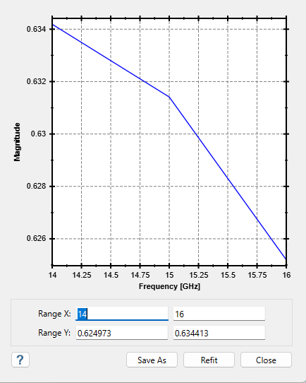
Plot S-Parameters
-
In the Analysis Workbench toolbar, select
 S-Parameters.
- In the S-parameters dialog select the input port as Waveguide Port 1 and out port as Waveguide Port 2.
-
Select the response type as Magnitude and click
Show to plot the S-parameter diagram.
Note: Users can also plot the Magnitude in dB scale and different types of response types.
Create Modal Electromagnetic Analysis
-
In the main menu toolbar, select
 Electromagnetics
Analysis >
Electromagnetics
Analysis >  Modal
Electromagnetics.
Modal
Electromagnetics.
- In the Setup dialog, enter 9 as the number of modes.
-
Click OK.
The new modal electromagnetics analysis appears in the Project Tree.
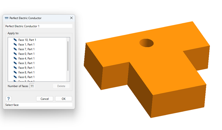
Create Perfect Electric Conductor
-
In the Analysis Workbench, click
 Perfect Electric Conductor.
-
In the dialog, select all faces of the model.
Tip: Hold Control on the keyboard and drag to select the entire model. SimSolid will select all the faces of the model.
Edit Solution Settings
- In the Analysis branch of the Project Tree, double-click Solution Settings.
- In the Solution Settings dialog, select Global from the Adaption dropdown menu.
- Click OK.
Run Analysis
- In the Project Tree, open the Analysis Workbench.
-
Click Solve.
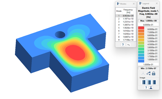
Review Modes
-
In the Analysis Workbench, click
Result
plot > Electric field > Electric field magnitude.
The Legend window opens and displays the contour plot. The Modes window opens and displays a list of modes.
-
Review the modes.
- Select a mode in the Frequency (Hz) window.
- Select the different modes and view the mode shapes.