SS-T: 4080 Transient Analysis
Tutorial Level: Advanced Run dynamic transient analysis in SimSolid.
- Purpose
- SimSolid performs meshless
structural analysis that works on full featured parts and assemblies, is
tolerant of geometric imperfections, and runs in seconds to minutes. In this
tutorial, you will do the following:
- Create Dynamic Transient Analysis.
- Model Description
- The following model file is needed for this tutorial:
- Transient.ssp
-
Figure 1. 
Open Project
- Start a new SimSolid session.
-
In the main window toolbar, click Open Project
 .
.
- In the Open project file dialog, choose Transient.ssp
- Click OK.
Create Modal Analysis
-
In the main window toolbar, click
 Modal Analysis.
- In the Number of modes window, specify the number of modes as 9.
-
Click OK.
The new modal analysis appears in the Project Tree.
Create Immovable Constraint
-
In the Analysis Workbench, select
 Constraints > Immovable support.
- In the dialog, verify the Faces radio button is selected.
-
In the modeling window, select the faces shown in Figure 2.
Figure 2. 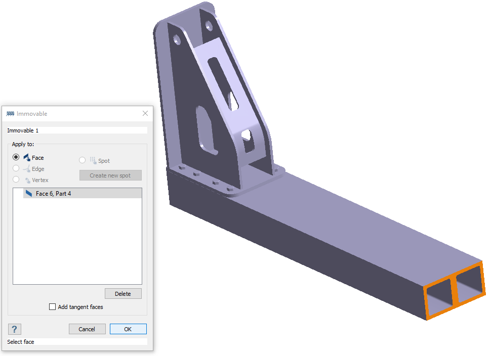
- Click OK.
Edit Solution Settings
- In the Analysis branch of the Project Tree, double-click on Solution settings.
- In the Solution settings dialog, for Adaptation select Global+Local in the drop-down menu.
- Click OK.
Run Analysis
- In the Project Tree, open the Analysis Workbench.
-
Click
 Solve.
Review Results
- In the Project Tree, Select the Modal 1 subcase.
-
In the Analysis Workbench, select
 Result plot > Displacement > Displacement
Magnitude.
The Legend window opens and displays the contour plot. The Frequency (Hz) window opens and lists the modes.
Result plot > Displacement > Displacement
Magnitude.
The Legend window opens and displays the contour plot. The Frequency (Hz) window opens and lists the modes.Figure 3. 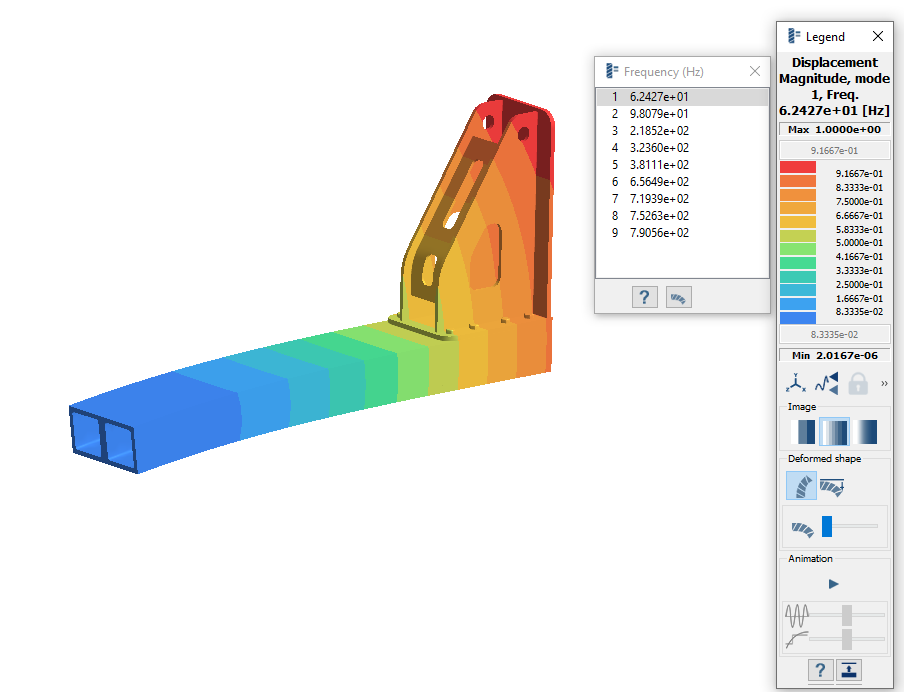
-
View the mode shapes.
- In the Frequency (Hz) window, highlight a mode in the list.
-
In the Legend, click
 (Start animation).
- Cycle between the other modes in the list.
Create Transient Analysis
-
In the main window toolbar, select
 Dynamics > Transient.
The Transient dynamics setup dialog opens. Link to the available Modal analysis result.Note: If multiple modal analyses with results are present in the design study, you must create the link manually. An example is shown in Figure 4.
Dynamics > Transient.
The Transient dynamics setup dialog opens. Link to the available Modal analysis result.Note: If multiple modal analyses with results are present in the design study, you must create the link manually. An example is shown in Figure 4.Figure 4. 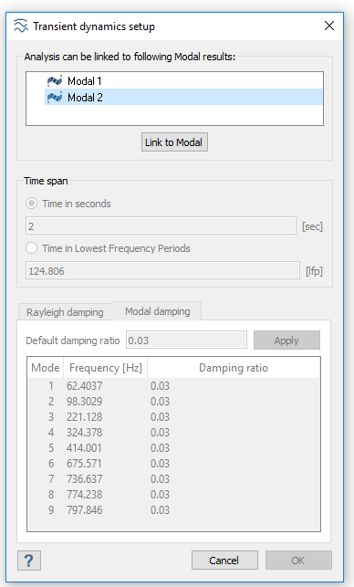
- For Time in seconds, enter 2.
- Go to the Modal damping tab.
- For Default damping ratio, enter 0.03.
- Click OK.
Create Time Function
- In the Project Tree, click on the Assembly branch to open the Assembly workbench.
-
In the workbench toolbar, click
 Time function.
-
In the Time function dialog, click
Standard.
Figure 5. 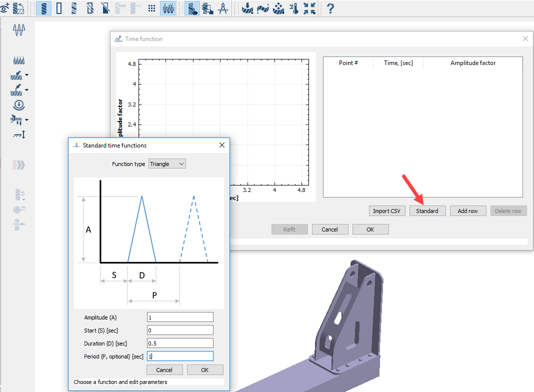
-
In the Standard time functions dialog, setup the
function.
- For select Triangle from the drop-down menu.
- For Amplitude, enter 1.
- For Start, enter 0.
- For Duration, enter 0.5.
- For Period, enter 1.
- Click OK.
Define Load
-
In the workbench toolbar, select
 Force/Displacement >
Force/Displacement.
Force/Displacement >
Force/Displacement.
- In the Force/Displacement dialog, select the Spot radio button.
-
Select the spot as shown in Figure 6.
Figure 6. 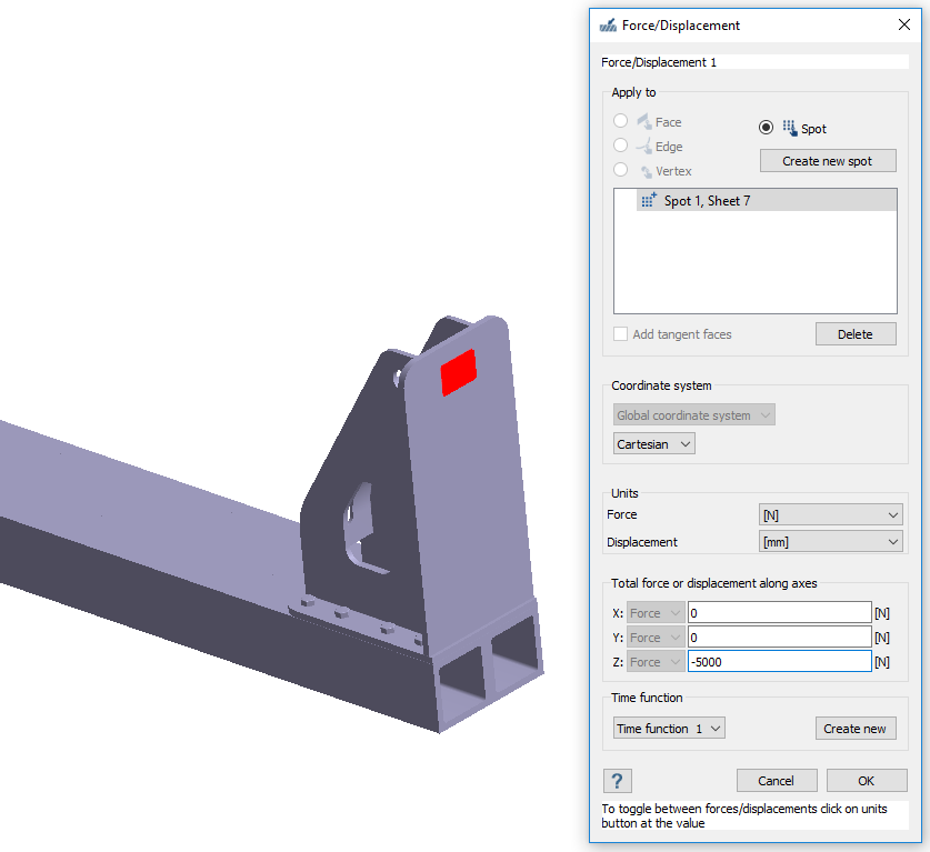
- Under Total force or displacement along axes, for Z enter -5000.
- Click OK.
Run Analysis
- In the Project Tree, open the Analysis Workbench.
-
Click Solve.
Review Results
- In the Project Tree, Select the Dynamic transient 1 subcase.
-
In the Analysis Workbench, select Result plot > Displacement > Displacement
Magnitude.
The Legend window opens and displays the contour plot. The Dynamics time response window opens. You can use the slider to change the time at which the result is being displayed.
Figure 7. 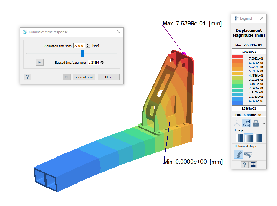
- In the Dynamics time response dialog, click Show at peak to view the maximum deformed shape and its contour.
-
Click to animate the model.