Axial Flux Motor
![]()
Description
This solution (hereinafter referred to as AFM solution) is used to quickly model axial flux machines (both the geometry and the mesh) and perform basic physics simulations (currently supports the following analyses: Cogging Torque, Back EMF, and Constant Speed).
- Defining the motor geometry
- Defining the test type
- Basic solution settings
- Initial materials will be automatically assigned to all created bodies and can be updated later.
- When the test type is set to Cogging Torque, the coupling circuit will not be created, and all meshed coils are considered as air.
- When the test type is set to Back EMF or
Constant Speed, a three-phase coupled circuit
will be automatically generated and fully defined when the motor
geometry meets the following common slot-pole number combinations:
- The number of slots per pole per phase = 0.5
Three coil bodies will be represented in the periodic motor model.
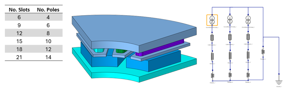
- The number of slots per pole per phase = 0.4
Six coil bodies will be represented in the periodic motor model.
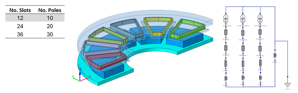
- When the number of slots per pole per phase is equal to other values, the user can manually set up the circuit to accommodate the desired fractional winding.
- The number of slots per pole per phase = 0.5
Motor geometry creation: AFM template
The AFM solution will use SimLab’s built-in AFM modeling tool (Create Axial Flux Machine) to quickly generate 3D motor geometry.
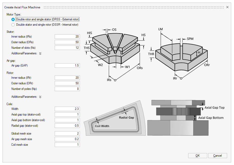
Please refer to the help page of the Create Axial Flux Machine tool for more information.
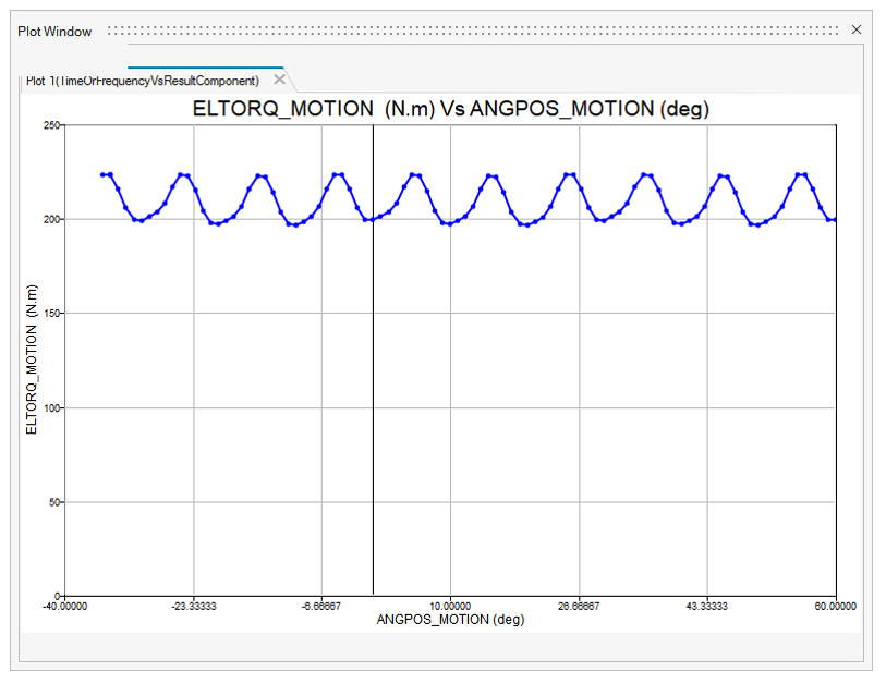
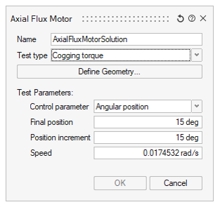
Test type 1: Cogging Torque
- Specify Angular position or Time as the Control parameter
- Define the simulation interval (the final value and the increment)
- Define the Speed
After validating the settings, SimLab will automatically create a 3D Transient Magnetic solution and all necessary LBCs (symmetry, periodicity, infinite region, magnets, motion).
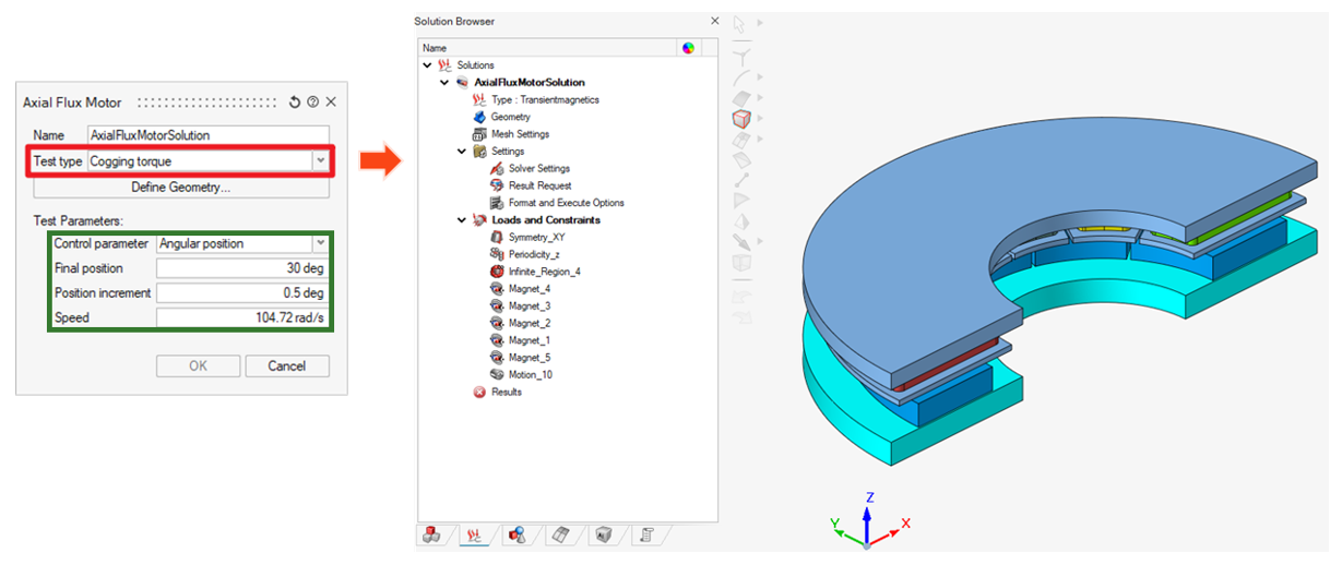
The solution is ready to be solved. Users can also modify the LBCs before solving.
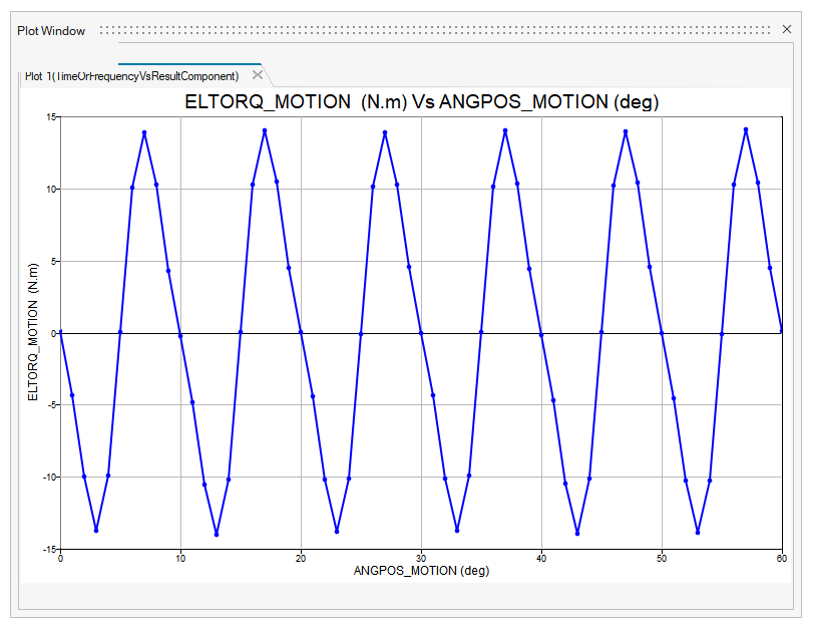
Example of Cogging Torque result:
Test type 2: Back EMF
- Specify Angular position or Time as the Control parameter
- Define the simulation interval (the final value and the increment)
- Define the Speed and the Initial Position
- Define the winding setting (only the number of coil turns is considered in this case)
After validating the settings, SimLab will automatically create a 3D Transient Magnetic solution and all necessary LBCs (symmetry, periodicity, infinite region, magnets, motion, and also the coupling circuit).
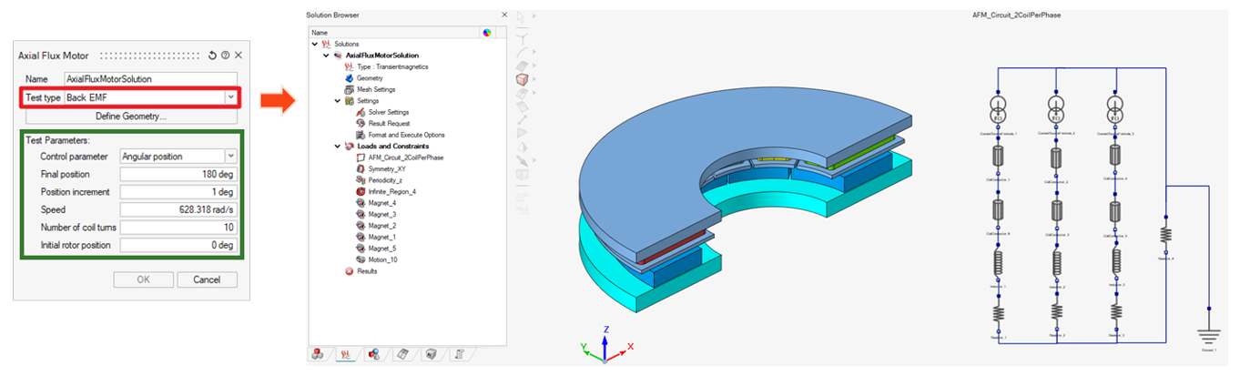
The solution is ready to be solved. Users can also modify the LBCs before solving.
Example of Back EMF result:
Test type 3: Constant Speed
- Specify Angular position or Time as the Control parameter
- Define the simulation interval (the final value and the increment)
- Define the Speed and the Initial Position
- Define the winding settings (current, control angle, number of coil turns)
After validating the settings, SimLab will automatically create a 3D Transient Magnetic solution and all necessary LBCs (symmetry, periodicity, infinite region, magnets, motion, and also the coupling circuit).
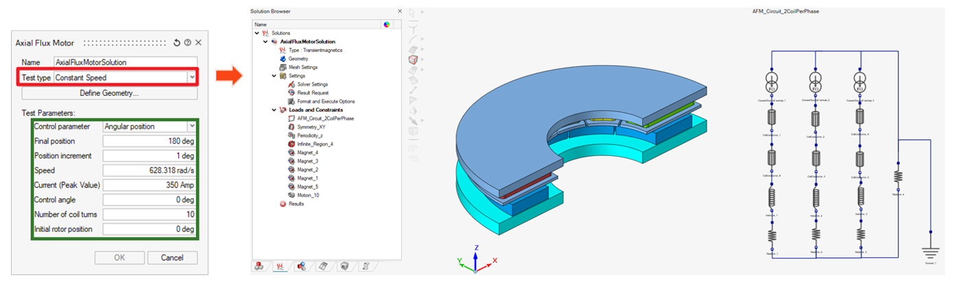
The solution is ready to be solved. Users can also modify the LBCs and also the circuit parameters before solving.
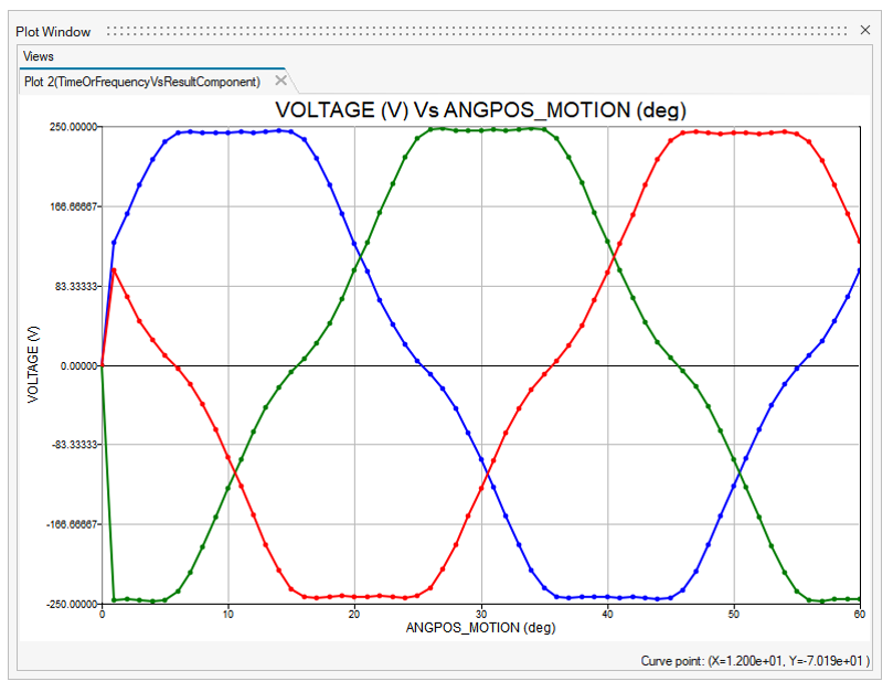
Example of Constant Speed result: