Sweep
![]()
Description
This is used to create a swept body.
- Solid body is created when faces are swept.
- Faces are created when edges are swept.
- Edges are created when vertices are swept.
Basic
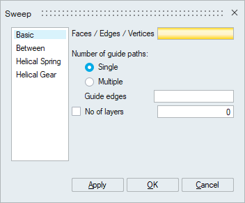
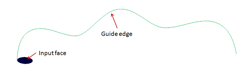
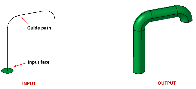
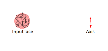
This is used to sweep faces or edges or vertices following the profile of the guide edge.
- Number of guide paths
- Single
Select faces or edges or vertices to sweep based on the profile of the guide edge.
- Multiple
- Select a face or edge to sweep.
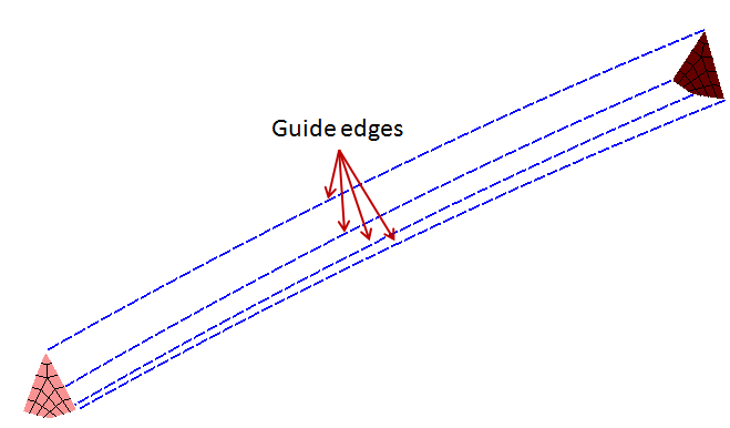
- Select two faces or two edges to sweep between them.Restriction:
- Supported only for three or four edged face.
- Not supported for edge forming closed loop.
- Number of vertices on the input face/edge should match with the number of guide edges.
- Single
- Number of layers
By default, the number of layers to sweep is obtained from the guide edge element count. You can also specify the desired number of layers.
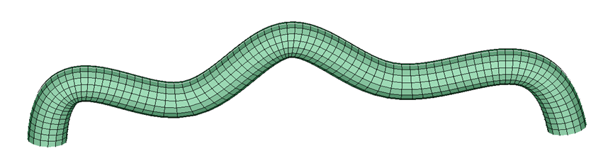
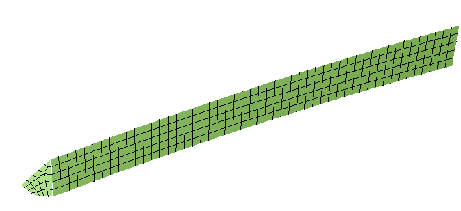
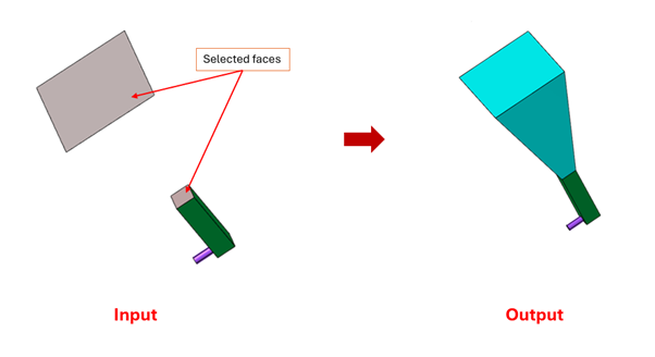
Example for single guide edge option
-
Mesh - Input
-
Output
- CAD - Parasolid
Example for multiple guide edge option
-
Input
-
Output
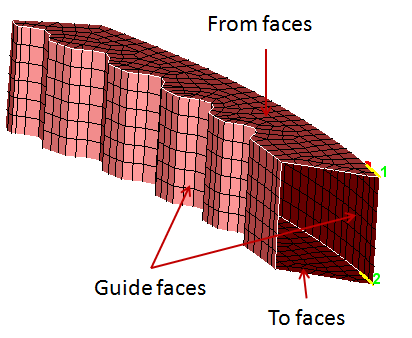
Between
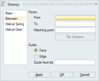
This option is used to sweep one set of faces to another set following the mesh profile of guide faces or edges. Both entities should have the same mesh patterns. An arrow will be displayed at both From and To faces. This specifies the direction to map the mesh between the two set of faces. The arrows should point in the same direction, otherwise use Flip Direction to correct it. Similarly the start point of the arrows should match, if not pick the corresponding matching point (node or vertex) on the To Faces. This option also supports CAD Parasolid faces for the model imported with save geometry in database option enabled. For CAD sweep, both From and To face should have same number of vertices.
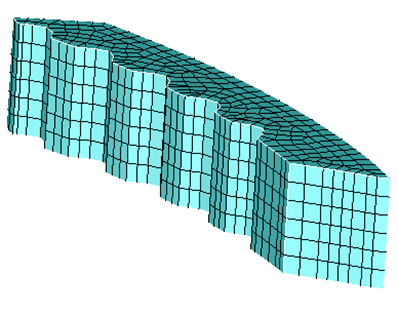
Example for guide faces option
-
Input
-
Output
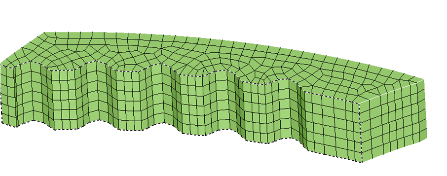
Example for guide edges option
-
Input
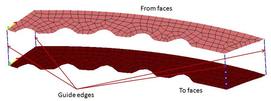
-
Output
CAD – Parasolid
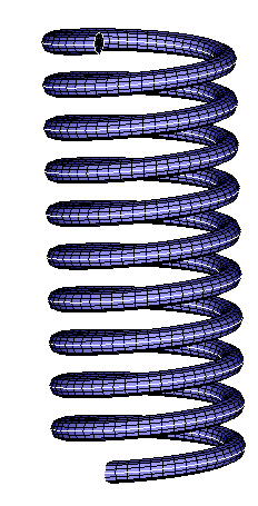
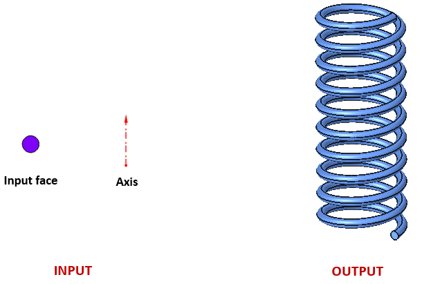
Helical Spring
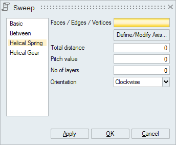
This option is used to create parts like drills, springs, and so on.
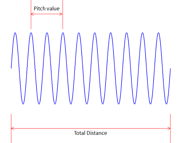
- Pitch value
The distance from the crest of one thread to the next thread.
- Number of layers
Number of layers required from crest of one thread to next thread.
Example
-
Mesh - Input
-
Output
- CAD - Parasolid
- CAD - Parasolid: Elliptical Sweep
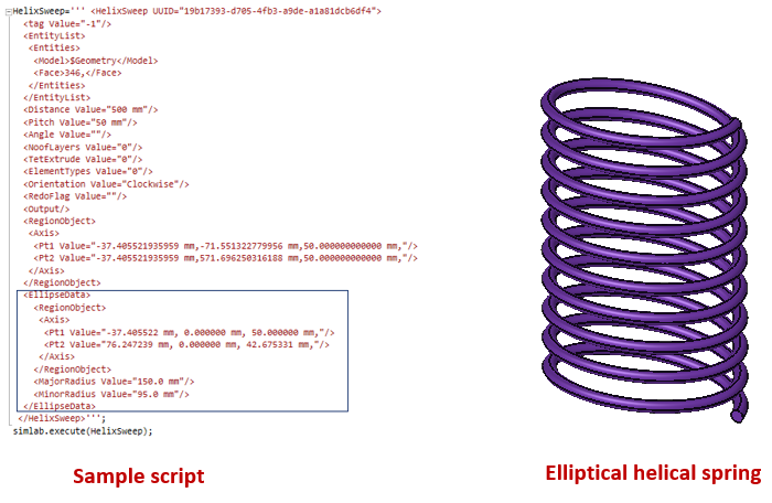
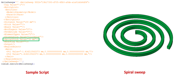
Special case – CAD Parasolid:
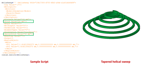
Spiral Sweep:
Spirally swept bodies can be created through script with the same parameters as in helical sweep. The only difference is that instead of pitch value, spiral pitch value must be entered as shown below.
Tapered helical Sweep:
Tapered and helically swept bodies can be created through script with the same parameters as in helical sweep. Here, both pitch value and spiral pitch value must be entered as shown below.
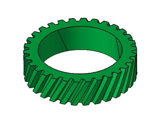
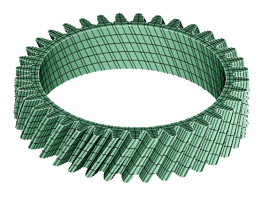
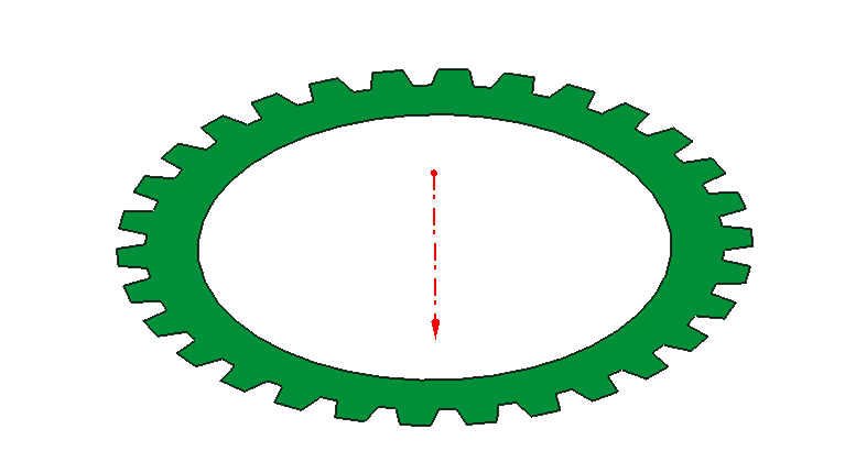
Helical Gear
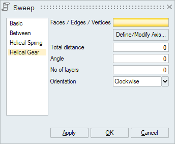
This option is used to create helical gear.
- Angle
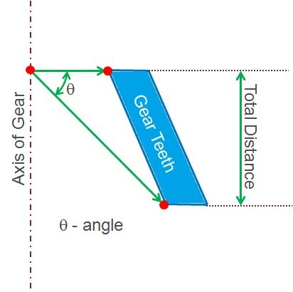
- Number of layers
Number of Layers required along the sweep direction for the total distance.
Example
-
Input
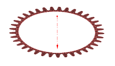
-
Output
CAD - Parasolid
- Input
- Output