Extrude
![]()
Description
This is used to create extruded bodies.
- Solid bodies are created when a face or face group is extruded.
- Faces are created when an edge or edge group is extruded.
- Edges are created when a vertex or vertex group is extruded.
The following option in Extrude is supported for CAD Parasolid bodies
- Normal
- Vector
- Upto Plane
- Upto Faces
Direction
This option is used to extrude faces or edges or vertices for a given distance in the specified direction.
- Normal
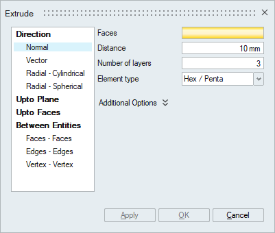
This option is used to extrude faces along the face normal direction.
- Vector
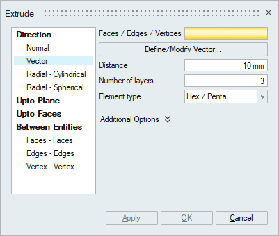
This option is used to extrude faces or edges or vertices along the defined direction.
- Radial - Cylindrical
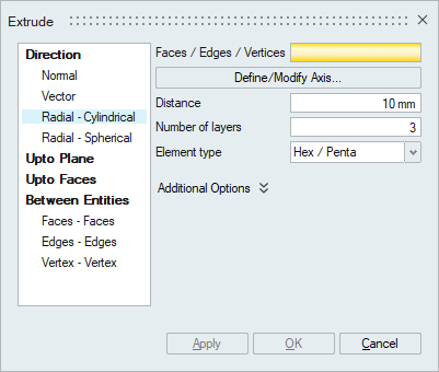
This option is used to extrude faces or edges or vertices along the radial direction.
- Radial - Spherical
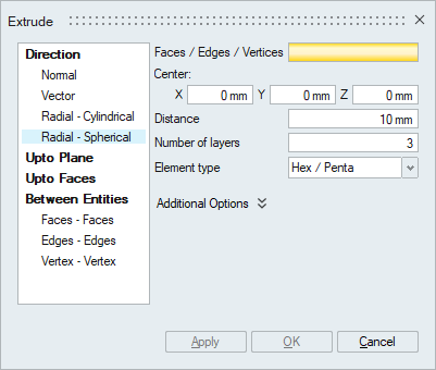
This option is used to extrude faces or edges or vertices along the spherical direction.
- Element type
Select the desired element type. The desired mesh is obtained based on this selection.
- The solid element types that are supported are Hex/Penta, Tet, Penta, Hex and Four Hex. If there is any mismatch between input face elements and the selected element type, the mesh on the input face will get modified. For example, If Tet element type is selected and the input face mesh contains any quad element, that will get modified to Tri elements.
- The sheet element types that are supported are Quad and Tri.
Note: Input entities mesh nodes will be made common with the extruded mesh. - Additional Options
- Match mesh on side faces: These faces act as guides for the sides of the extruded solid body. The guide faces should contains only iso quad elements. Supported only for face or face group input.
- Inflate: This is used to extrude in both directions. Extrude will happen on each direction for half of the user given distance. Supported only for face or face group input.
- Merge input and extruded solid body: By default the solid elements will be created in a new body. This option is used to create the solid elements in the selected faces body itself, provided the selected faces belong to a solid body.
- Create body from side and top faces: This toggle is used to create surface bodies from the extruded side and top faces. It will have shared nodes between these surface bodies and extruded body. Supported only for face or face group input.
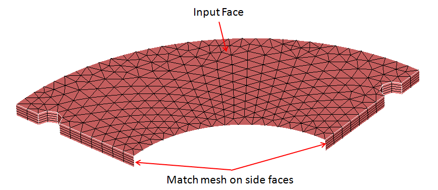
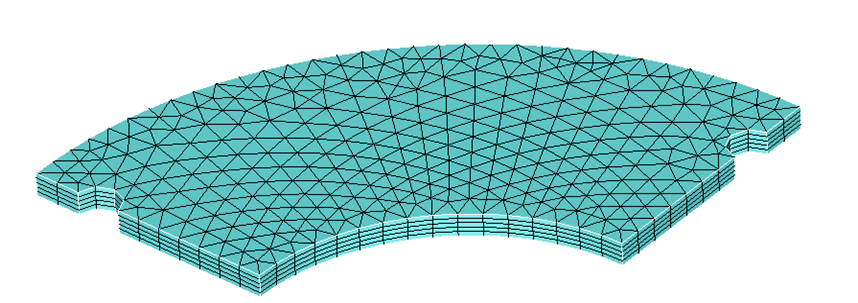
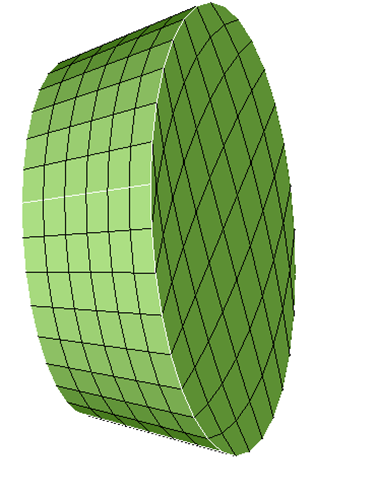
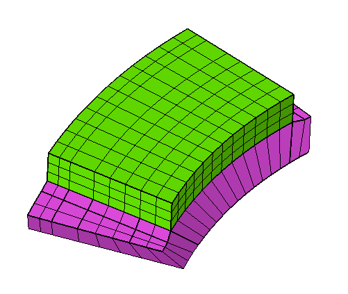
Example: Match mesh on side faces
In this example the input faces are extruded for a distance of 5 with 5 layers of elements.
- Input
- Output
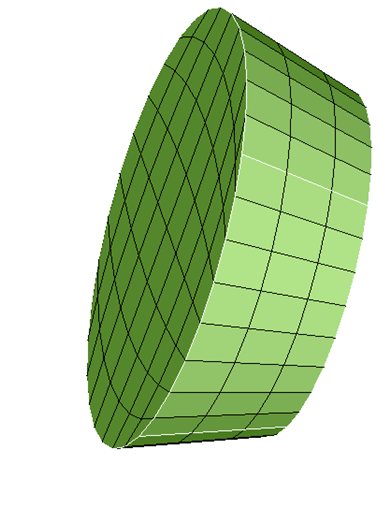
Example: Inflate
In this example the input faces are extruded for a distance of 10 with 5 layers of elements.
- Input
- Output
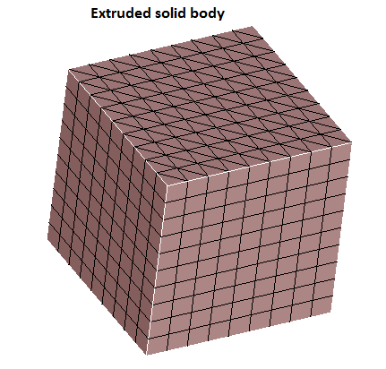
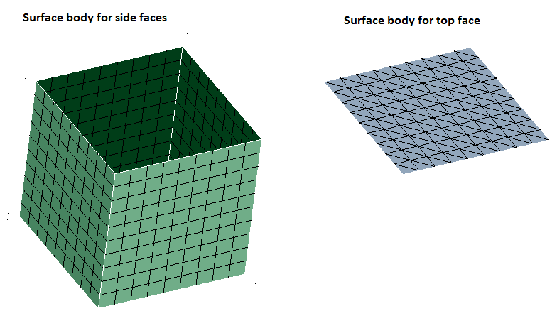
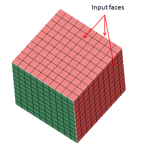
Example: Create body from side and top faces
- Input
- Output
Following three bodies are created for this toggle.
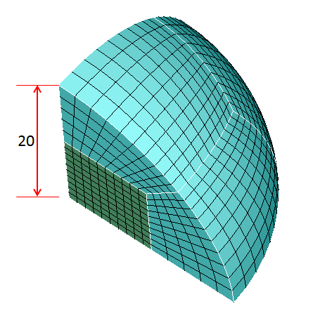
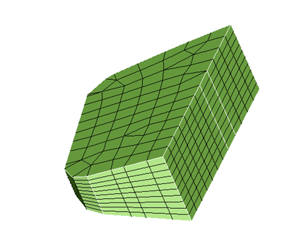
Example: Radial - Spherical
The shown faces are extruded along the spherical direction for a distance of 20 with 5 layers of elements.
-
Input
- Output
Example: CAD (Parasolid)
-
Input
- Output
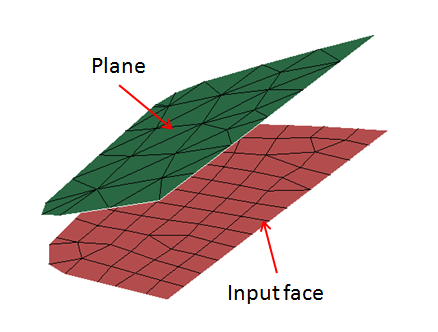
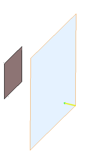
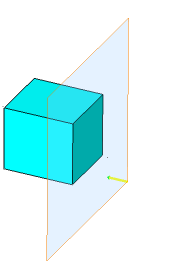
Upto Plane
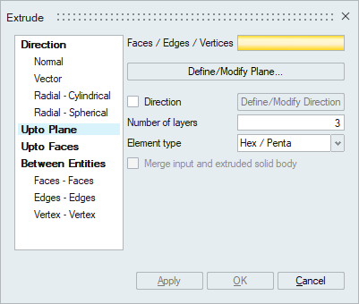
This is used to extrude faces or edges or vertices up to the defined plane along the element normal or user defined direction. The direction must be defined in case of edge or vertex input.
- Element type
Select the desired element type. The desired mesh is obtained based on this selection.
- The solid element types that are supported are Hex/Penta, Tet, Penta, Hex and Four Hex. If there is any mismatch between input face elements and the selected element type, the mesh on the input face will get modified. For example, If Tet element type is selected and the input face mesh contains any quad element, that will get modified to Tri elements.
- The sheet element types that are supported are Quad and Tri.
Note: Input entities mesh nodes will be made common with the extruded mesh. - Merge input and extruded solid body
By default the solid elements will be created in a new body. This option is used to create the solid elements in the selected faces body itself, provided the selected faces belong to a solid body.
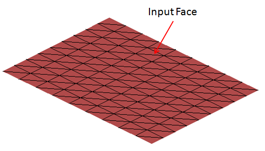
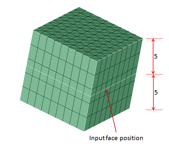
Example - Mesh
-
Input
- Output
Example - CAD (Parasolid)
-
Input
- Output
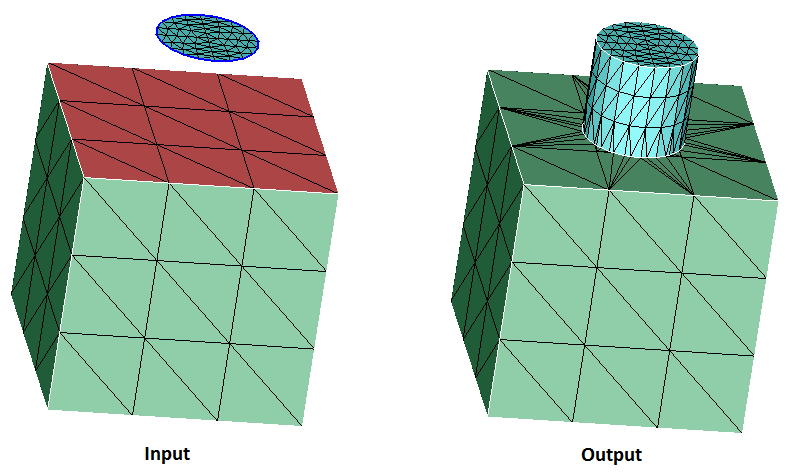
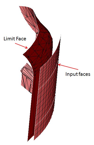
Upto Faces

This is used to extrude faces or edges or vertices up to the limit faces along the element normal or user defined direction. Users can select either CAD or mesh faces as the Limit faces. The direction must be defined in case of edge or vertex input.
- Connect to limit faces
This option is supported only for edge input. This option is used to connect the extruded faces to the limit faces and delete the internal faces automatically.
Example
- Element type
Select the desired element type. The desired mesh is obtained based on this selection.
- The solid element types that are supported are Hex/Penta, Tet, Penta, Hex and Four Hex. If there is any mismatch between input face elements and the selected element type, the mesh on the input face will get modified. For example, If Tet element type is selected and the input face mesh contains any quad element, that will get modified to Tri elements.
- The sheet element types that are supported are Quad and Tri.
Note: Input entities mesh nodes will be made common with the extruded mesh. - Merge input and extruded solid body
By default the solid elements will be created in a new body. This option is used to create the solid elements in the selected faces body itself, provided the selected faces belong to a solid body.
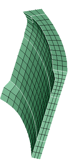
Example
- Input
- Output
- Input
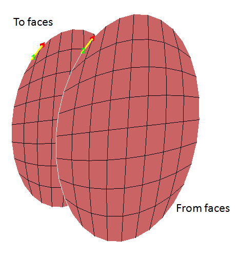
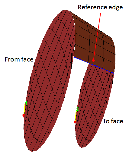
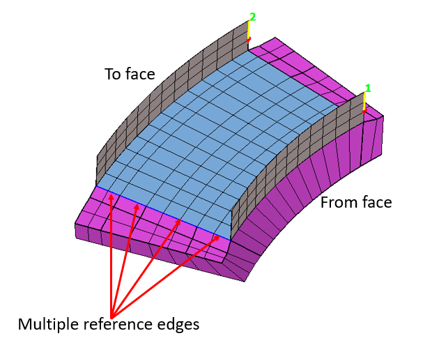
Between Entities: Faces - Faces
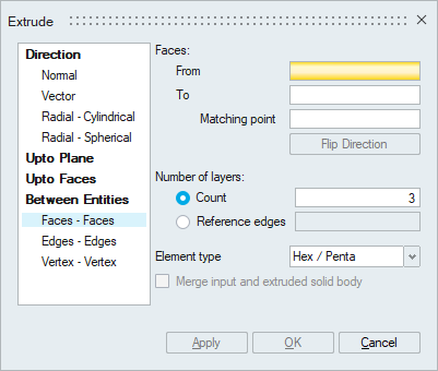
This option is used to extrude one set of faces to another set. Both entities should have the same mesh patterns. An arrow will be displayed at both From and To faces. This specifies the direction to map the mesh between the two set of faces. The arrows should point in the same direction, otherwise use Flip Direction to correct it. Similarly the start point of the arrows should match, if not, pick the corresponding matching point (node or vertex) on the To Faces.
- Number of layers
User can input number of layers or reference edges. If reference edges are given as input, the mesh on the edges acts as guide for the extrude layers.
- Element type
Select the desired element type. The desired mesh is obtained based on this selection. The solid element types that are supported are Hex/Penta, Tet, Penta, Hex and Four Hex. If there is any mismatch between input face elements and the selected element type, the mesh on the input face will get modified. For example, If Tet element type is selected and the input face mesh contains any quad element, that will get modified to Tri elements.
Note: Input entities mesh nodes will be made common with the extruded mesh. - Merge input and extruded solid body
By default the solid elements will be created in a new body. This option is used to create the solid elements in the selected faces body itself, provided the selected faces belong to a solid body.
Example 1
- Input
- Output
Example 2
- Input
- Output
- Input
- Output
Between Entities: Edges - Edges
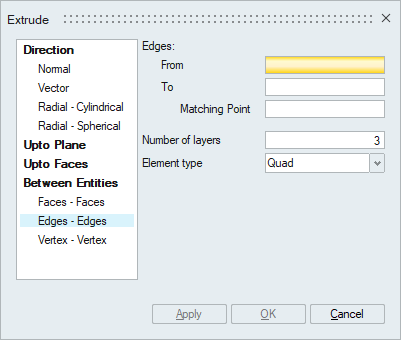
This option is used to extrude one set of edges to another set. Both entities should have the same mesh patterns. An arrow will be displayed at both From and To edges. This specifies the direction to map the mesh between the two set of edges. The arrows should point in the same direction, otherwise use Flip Direction to correct it. Similarly the start point of the arrows should match, if not pick the corresponding matching point (node or vertex) on the To edges.
Between Entities: Vertex - Vertex
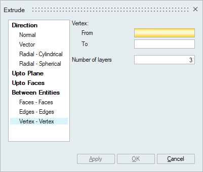
This option is used to extrude between two vertices to create a wire body.