Parameters
Description
SimLab scripts can be created using explicit values in dialogs. To execute the script for variations of these values or expressions, Parameters can be used. Before creating scripts, string, real and integer Parameters can be defined. These parameters can be used when creating the script.
Expressions should start with the '$' symbol.
There are two type of parameters:
- Pre-defined Parameters
- User-defined Parameters
Predefined Parameters
These are the Parameters which are already defined by SimLab for Automation.
List of Pre-defined Paramters
- PI - 3.14159265358979323846
- E - 2.71828182845904523536
- GAMMA - 0.57721566490153286060 (Euler)
- DEG - 57.29577951308232087680 (deg/radian -> 180/PI)
- PHI - 1.61803398874989484820 (golden ratio)
- SIN
- COS
- TAN
- ATAN
- LOG
- LOG10
- EXP (E power)
- SQRT
- INT
- ABS
- MAX
- MIN
Examples
- $PI+PI-> Valid
$PI+$PI->Invalid (Use the '$' only as the starting symbol of an expression)
- SIN -> Ex: use $SIN(45+45), user defined parameters can also be used to
represent the angle
$SIN(theeta) -> Valid
$SIN($theeta) -> Invalid
- $LOG(2.71828182845904523536) = 1
$LOG10(100) = 2
- EXP -> E power 2 (Value of E is 2.71828182845904523536)
$EXP(2) = 7.389056
- $SQRT(100) = 10
- INT -> Gives the integer value. Ignores the fractional part of the given number.
It will not round off the given number.
$INT(12.9999) = 12
- ABS -> Gives the positive value even the evaluated value is
negative.
$ABS(-10) = 10
- MAX -> Gives the maximum value from the given two values
$MAX(10, 12) = 12
- MIN -> Gives the minimum value from the given two values
$MIN(10, 12) = 10
User-defined Parameters
Users can define the parameters by any one of the following method.
- Parameters Dialog - Project Menu > Parameters
- Parameters Browsers - Model Browser > Parameters
Parameters Dialog
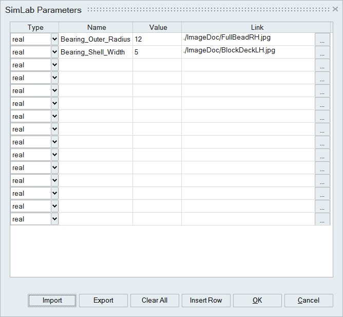
- Type
To specify the type of the parameter to be defined(integer, real, and string).
- Name
To specify the name of the parameter.
Parameter name should start with an alphabet ([a...z],[A...Z]) and it can have combination of numbers (0...9) and underscore characters("_").
Pre-defined parameters names should not be used.
- Value
To specify the value of the parameter.
- Link
User can link an image that describes the parameter. Double click on the cell will pop up the image in the browser.
- Insert Row
Additional rows can be inserted by using this option.
- Import and Export
The Parameters can be read from the xml file by using the "Import" option. In the same way, these parameters can be written into an xml file by using the "Export" option.
Import is also supported for:
-
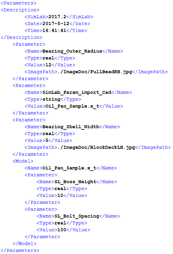
Sample Parameter xml File content
- Sample Parameter csv File content

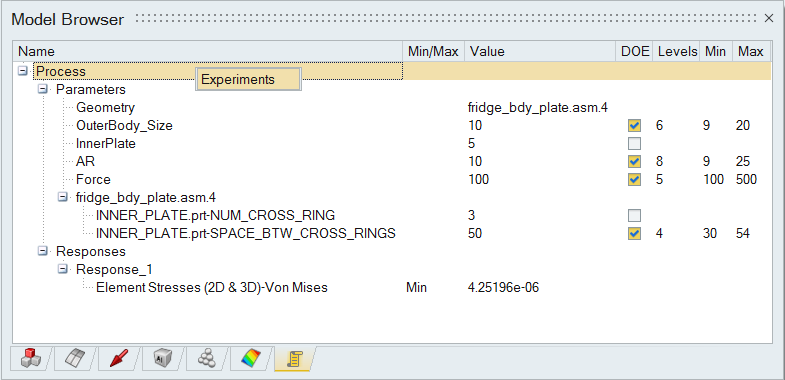
Validate – "Validate" option in right click on CAD(CATIA/Creo/NX) model's name allows to validate the model for a range of design variables.
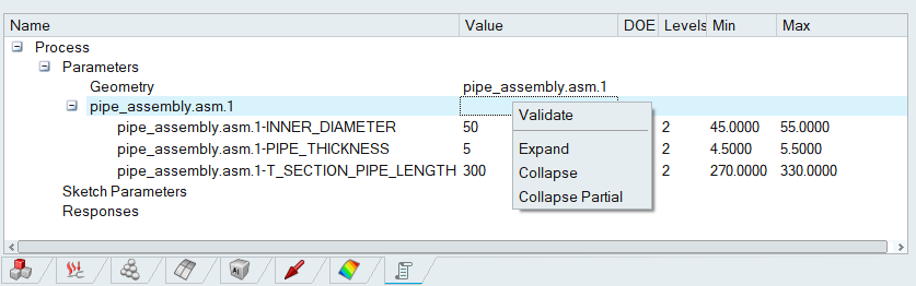
Select design parameters from "DOE" column and set "Levels", "Min" and "Max" value to validate model.
-
- Right Click Options
- Root folder: Create,Import,Export,Delete.
- Parameter object: Show Image,Delete.
- Example Expressions
- $len -> Valid
len -> Invalid
- $len + len -> Valid
$len + $len -> Invalid
- $len + 3 -> Valid
len + 3 -> Invalid
- $10 + 3 -> Valid
10 + 3 -> Invalid
- $10 -> Valid
- $len -> Valid
- Responses
DOE study output response will be listed.
Right click on the response title will have the following options.
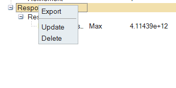
- Export – This option will export the output response in a xml file.
- Update – This option will update values for the output response from the base run.
- Delete – This option will delete all the response.
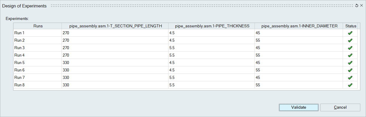
- Experiments
SimLab provides a mechanism to record a modeling process in a session file. This process can be parametrized using CAD and SimLab parameters. After a process is recorded, the recording can be played for variations of the CAD and Simlab parameters. Each variation is an experiment. The result from all these experiments can help make design decisions. DOE (Design of Experiments) tool allows users to setup the experiments.
To setup DOE, there should be a recording of the process in the form of JavaScript or Python script. The script file should reside in a folder, referred to as working folder. The scripts should use CAD and SimLab parameters which can be changed for each experiment. The "DOE Setup" dialog can be used to create the experiments.
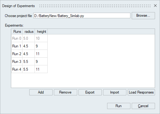
Setting up DOE
Select the script file(*.py, *.js, *.xml, *.sls).It will consider the parameter browser inputs of DOE, Min ,Max and Runs values which is specified by user and based on all the combinations, experiments will be inserted in the table which user cab edit.Each row in the table refers to either a SimLab parameter or CAD dimension (CAD parameter) or response. The "Experiments" table lists the parameters and rersponses used for each run. Experiments can be removed or added using the "Add" and "Remove" button. The list of experiments in this table can be exported into an xml file and saved. It is also possible to import a saved DOE table if it can be reused.Once we execute all the runs "Load Responses" button will display the output response value of each run for the selected process.
For each run, it updates the response value and it creates separate folder for each run and store the following files under that folder.
- Updated CAD geometry
- Results file