Parameters
Parameters can be created and applied to a variety of tools available in SimLab. Users can create a parameter dependent on another parameter or a mathematical expression, which will cascade changes and update accordingly. This allows users to quickly iterate and compare design concepts by tweaking the values of the parameters.
Manage Parameters
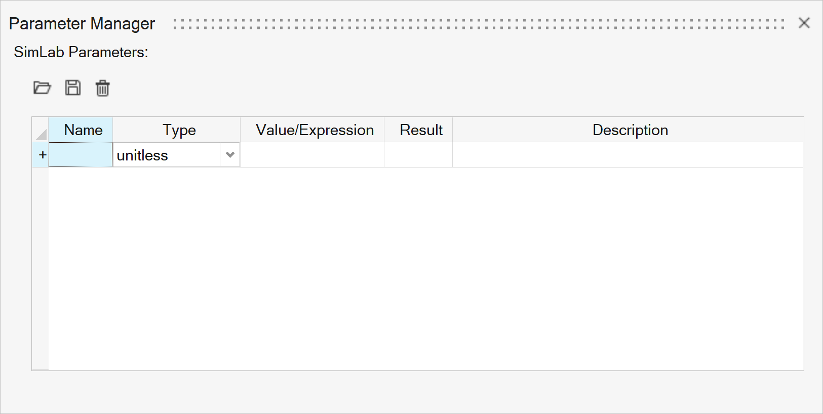
Use the Parameter Manager to edit, create, delete parameters, and import or export parameters in .xml format.
- On the Automation ribbon, select the Parameters option.
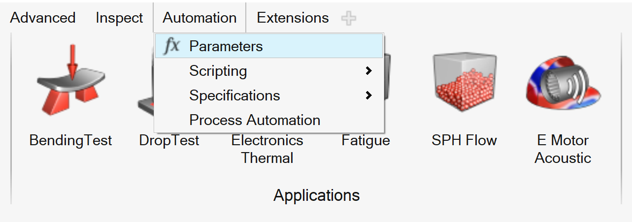
The Parameter Manager is displayed.
- User can do the following in the Parameter
Manager:
Import
Click
 to import the parameter file (.XML). If the
imported parameters are already defined, then the values will be updated
from the XML file.
to import the parameter file (.XML). If the
imported parameters are already defined, then the values will be updated
from the XML file.Export
Click
 to export the
parameters as a .XML file.
to export the
parameters as a .XML file.Delete
Select one or more parameters and click
 to delete the selected parameters.
Create / Edit
-
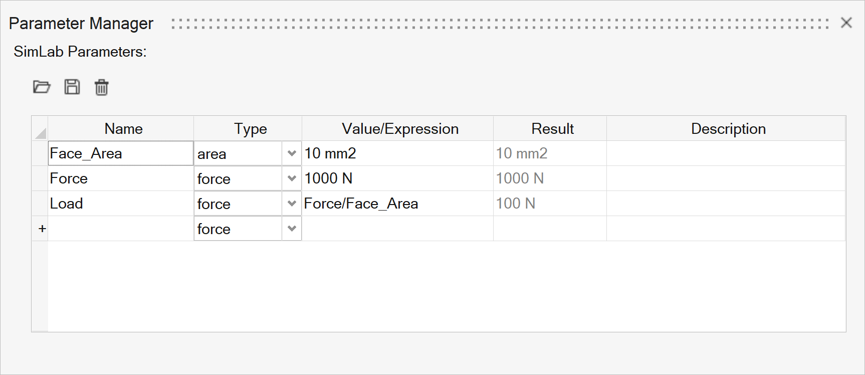
Enter the parameter name by clicking a cell in the “Name” column, similarly, enter the value in the “Value/Expression” column to create the parameter. Note: Name or value cannot be empty.
- User can create expressions using the following built-in
constants and functions,
- PI|E|GAMMA|DEG|PHI|SIN|SIND|ASIN|ASIND|COS|COSD|ACOS|ACOSD|TAN|TAND|ATAN|ATAN2|ATAN2D|LOG|LOG10|EXP|SQRT|INT|ABS|MAX |MIN |VALID|MODULO|TRAPEZ|TRAPEZPER
- PI - 3.14159265358979323846
- E - 2.71828182845904523536
- GAMMA - 0.57721566490153286060 (Euler)
- DEG - 57.29577951308232087680 (deg/radian -> 180/PI)
- PHI - 1.61803398874989484820 (golden ratio)
- SIN
- SIND
- ASIN
- ASIND
- COS
- COSD
- ACOS
- ACOSD
- TAN
- TAND
- ATAN
- ATAN2
- ATAN2D
- LOG
- LOG10
- EXP (E power)
- SQRT
- INT
- ABS
- MAX
- MIN
- VALID
- MODULO
- TRAPEZ
- TRAPEZPER
-
Note:
- Parameter Name should contain only the combination of numbers and underscore char as [a-zA-Z][0-9][_].
- Parameter Name should not be built-in constant or function.
-
- CAD Parameters
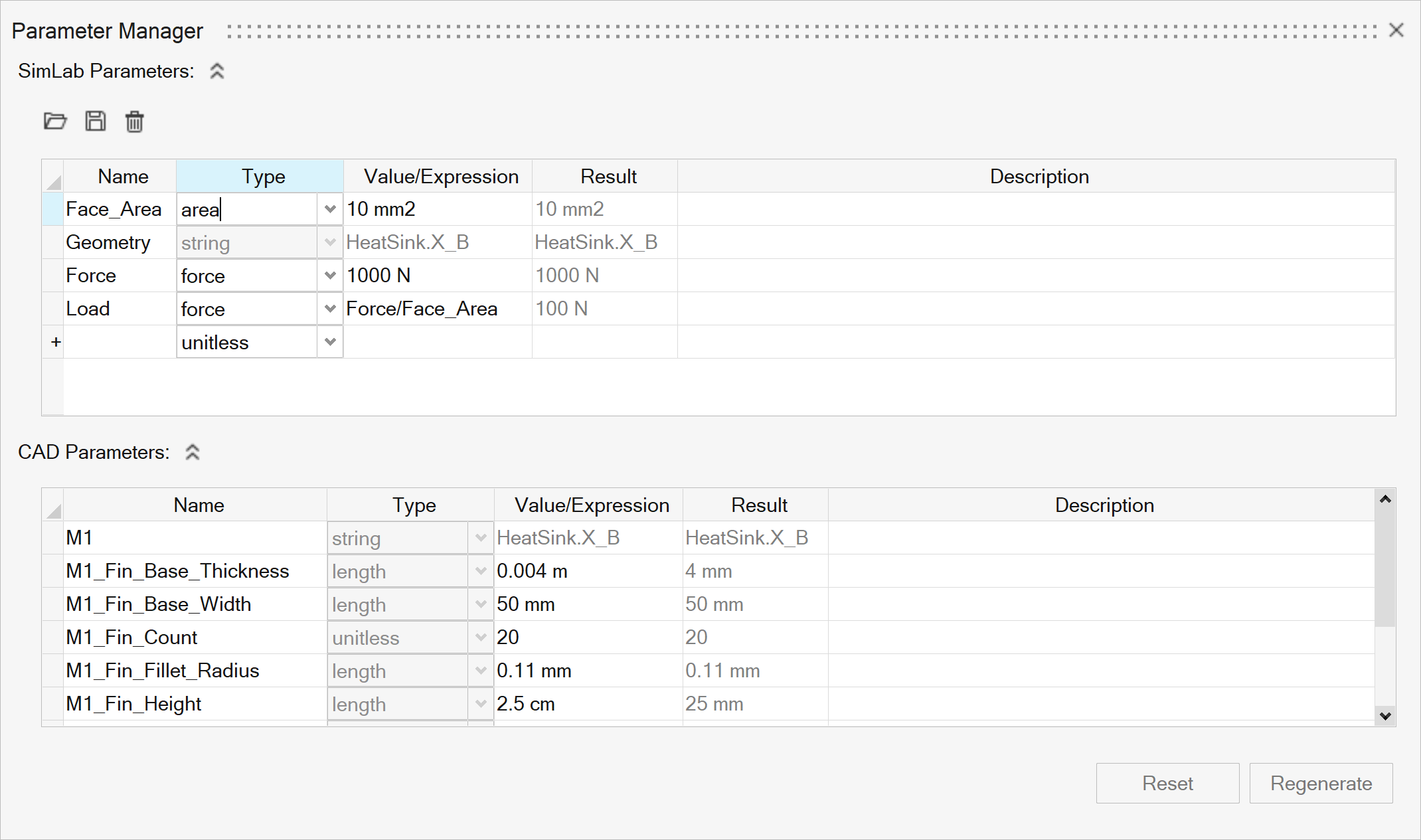
General:
- CAD Model design parameters will be listed under the “CAD Parameters” in the Parameter Manager.
- When the CAD models with design parameters are imported, a
parameter containing the model’s name will be created.
For example,
M1 = Model1.prt,
M2 = Model2.prt etc…
- It will act as an alias prefix for each model parameter. This
parameter name “M1 or M2” will be prepended along with “_” to
the corresponding parameter names of the CAD model.
For example,
If ‘Width’ is the CAD parameter of ‘Model1.prt’, when imported in SimLab an alias name ‘M1_Width’ will be created.
Similarly, if ‘Height’ is the CAD parameter of ‘Model2.prt’, the alias name will be ‘M2_Width’.
- In the case of the sketch parameters, the same will be followed.
Currently, all the sketches will be imported under one model
name ‘Sketches’, so only one alias parameter will be
created.
For example,
M3 = Sketches
If ‘CircleDia’ is the sketch parameter, its alias name will be ‘M3_CircleDia’.
- If an existing SimLab parameter starts with M1, then the next available numbered alias will be used “M2, M3, etc..”.
- For the CAD parameters, the unit type will be imported from CAD system. Currently the length and Angle parameters are imported, remaining parameters will be imported as unitless. For sketch parameters, the unit type will be taken from the ‘Sketch > Variable Manager’.
- Once the model is deleted, these parameters will be deleted.
Regenerate:
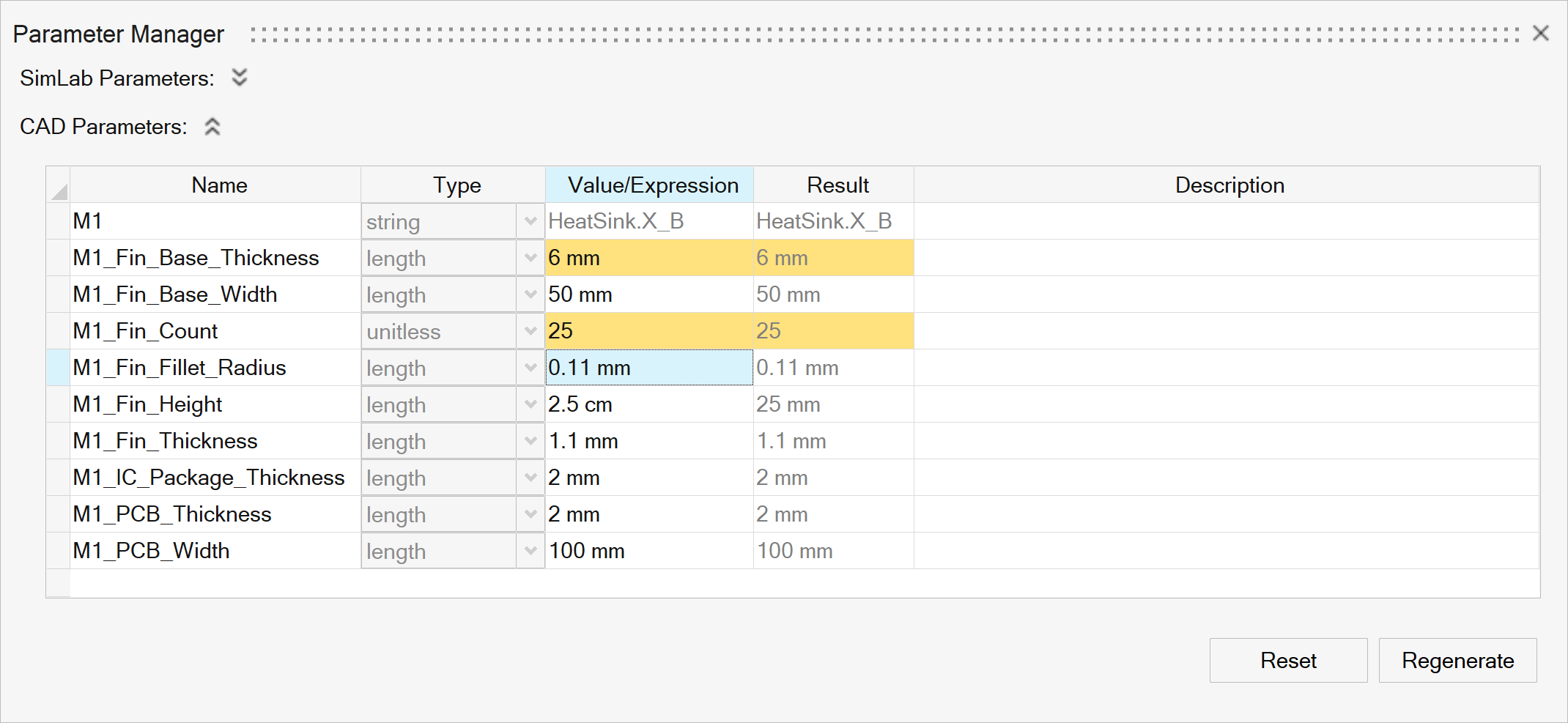
- The CAD parameter value can be changed. The modified cells will be highlighted in yellow color.
- Click the Regenerate option to update the CAD geometry with the modified value.
- Reset option can be used to restore the original values of the parameters.
Tips
- To list the parameters available in the Parameter Manager, just type the
parameter name in SimLab tool’s line edit, a drop-down will be shown with
the matching parameters in accordance with the line edit type.
- For example, when user clicks in the ‘Height’ line edit, only the
parameters of type ‘Length’ will be listed.
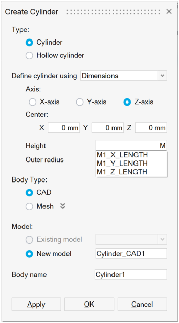
- Or do Right-Click > Select parameter
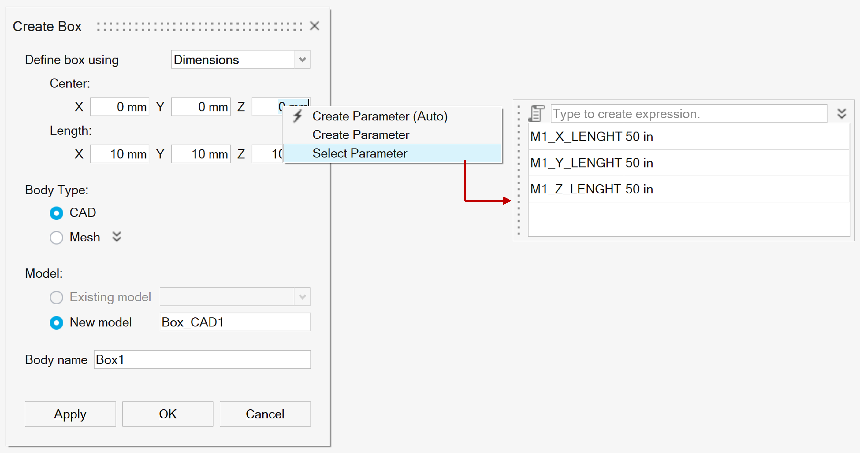
- For example, when user clicks in the ‘Height’ line edit, only the
parameters of type ‘Length’ will be listed.