Create Weld Bead
![]()
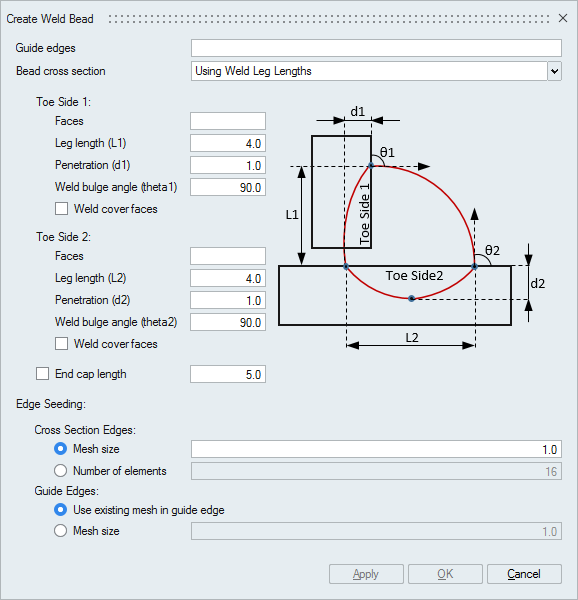
Dialog Box
This tool is used to create weld connection between two bodies by creating weld bead with circular cross section. Circular cross section will be swept along the guide edges. The guide edges should be continuous. The weld bead body will be created with tri elements.
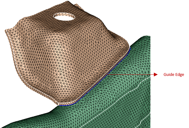
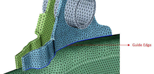
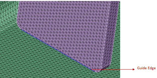
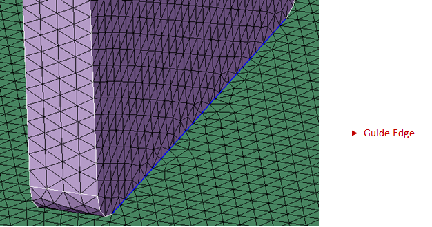
Guide edges
User can select the topology edges as guide edges. Bead with selected cross section will be swept along the path of these edges.
Edge Seeding
Cross Section Edges - User can input either mesh size or number of elements along cross section.
Guide Edges - Mesh size along the path of weld bead can be controlled in two ways. "Use existing mesh in guide edge" will follow the mesh as in the guide edges or user can input the mesh size along the path of weld bead.
Bead cross section using weld leg lengths
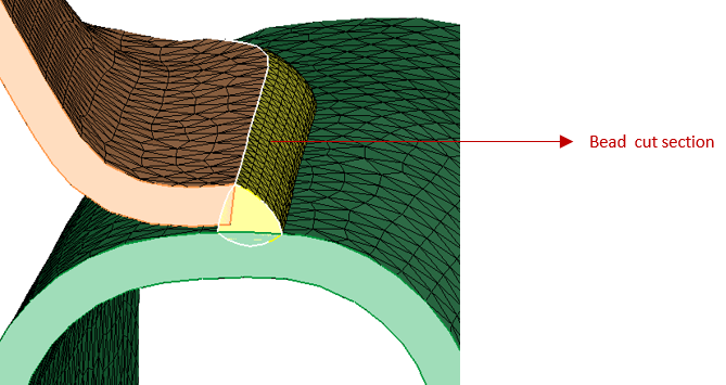
User can define the bead cross section by specifying the leg lengths, weld bulge angle and penetration depth on toe side faces.Select faces on toe sides, hence bead will follow the curvature of these toe side faces along the guide edge path. If the weld bulge angle is given more than 90 degrees then it will create concave bead. To cover full face on the toe side, turn ON the weld covers face toggle.
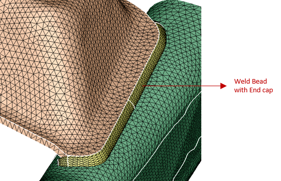
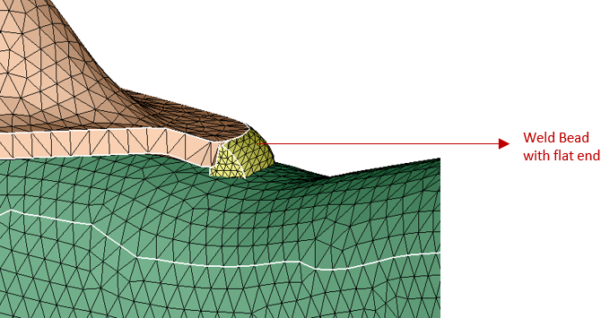
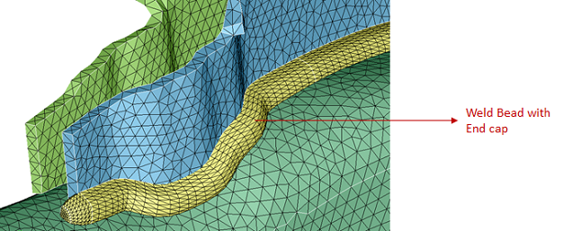
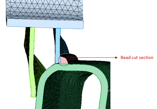
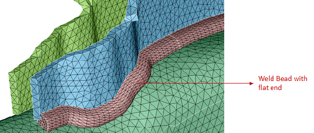
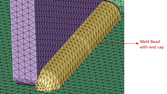
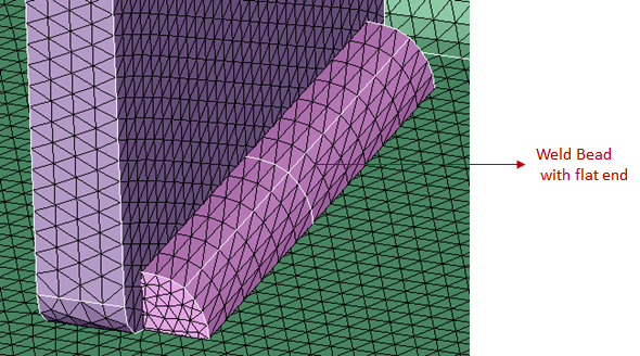
If the weld path(guide edges) is not closed loop then user have the option to create bead either with or without end cap. User can specify end cap length to create bead with end caps by turning ON the end cap length toggle. If this toggle is turned OFF, bead with flat end will be created.
Example| Input | Output |
|---|---|
 |
|
 |
|
 |
Bead cross section using weld throat thickness
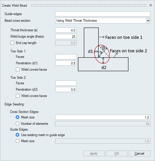
User can define the simple bead cross section by specifying the throat thickness, weld bulge angle and penetration depth on toe side faces.
Select faces on toe sides, hence bead will follow the curvature of these toe side faces along the guide edge path. To cover full face on the toe side, turn ON the weld covers face toggle.
If the weld path(guide edges) is not closed loop then user have the option to create bead either with or without end cap. User can specify end cap length to create bead with end caps by turning ON the end cap length toggle. If this toggle is turned OFF, bead with flat end will be created.
Example| Input | Output |
|---|---|
|
|
|
|
|
Bead cross section - Circular
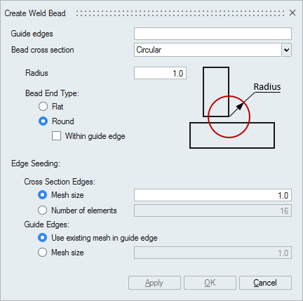
Radius - Radius of circular bead cross section.
Bead End Type - User can create beads with different end types.
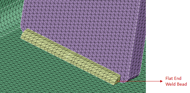
- Flat - End of weld bead will be flat.
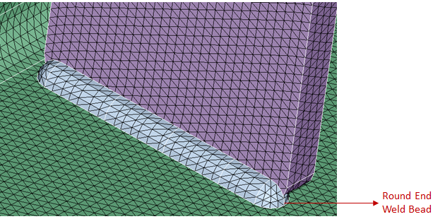
- Round - End of weld bead will be round.
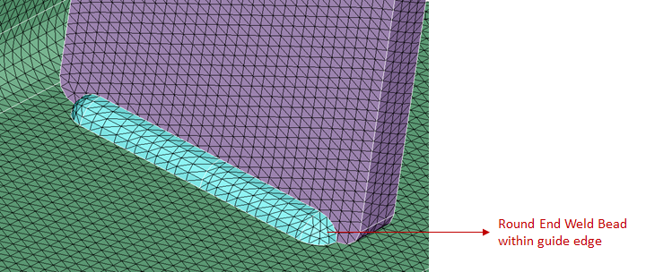
- Round within guide edge - End of weld bead will be round and it will be created within the guide edges.
| Input | Output |
|---|---|
|
|
|
|
|
Bead cross section - Detailed
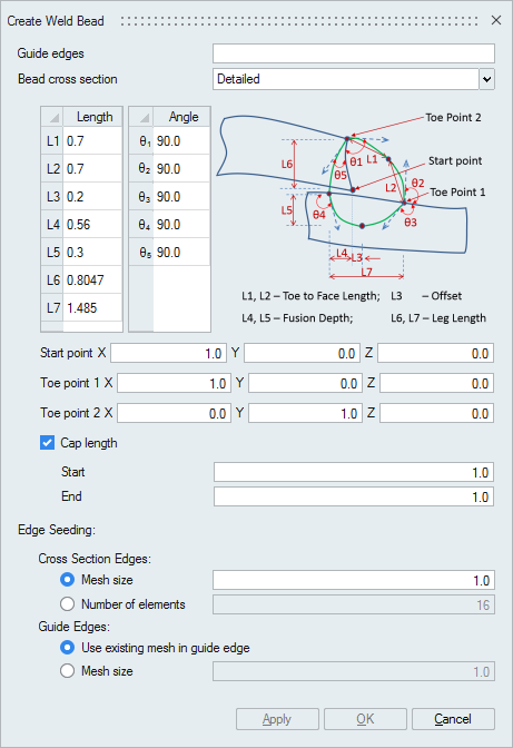
User can define the detailed bead cross section by specifying the length and angle parameters.
To position the cross section user has to select three unique points (start point, toe point1 and toe point2) by picking nodes/vertices.
If the weld path(guide edges) is not closed loop then user have the option to create bead either with or without end cap. User can specify start and end cap lengths to create bead with end caps by turning ON the cap length toggle. If this toggle is turned OFF, bead with flat end will be created.
Example| Input | Output |
|---|---|
|
|
|
|
|