Wire Bonding
![]()
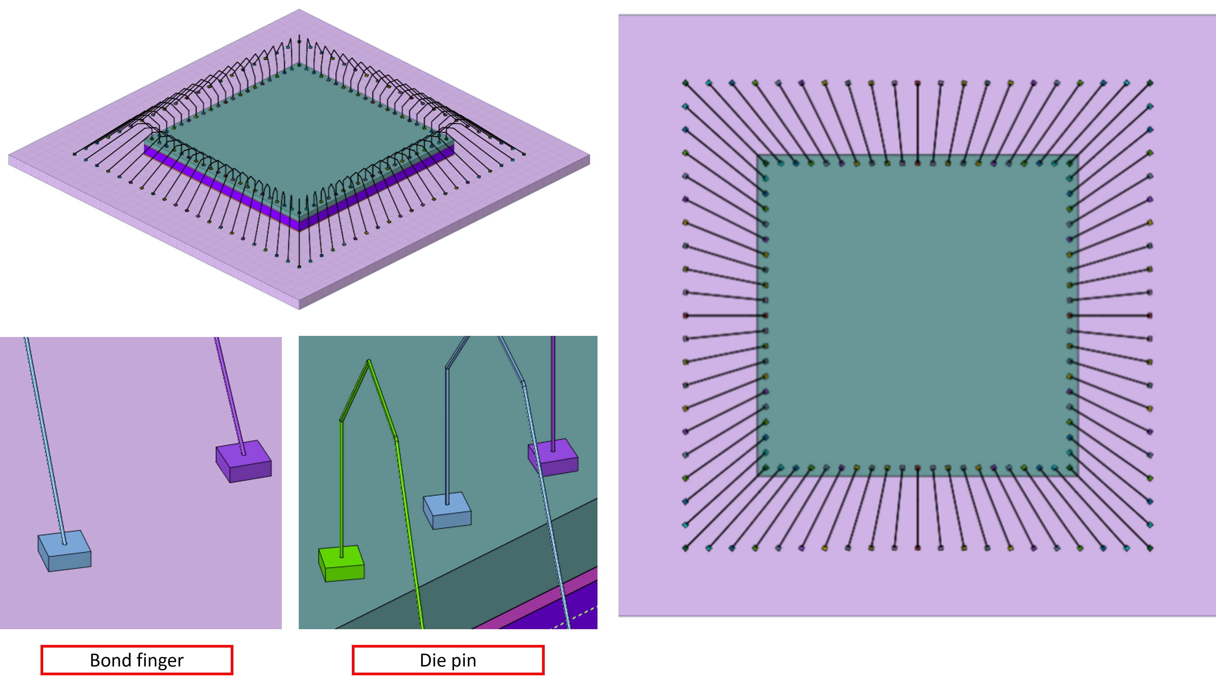
This tool facilitates the creation of fine wire connections by importing data from a CSV file. The file contains the start and end points for each wire, along with additional parameters related to die pin and bond finger. Users can define the wire shape or profile by specifying a series of control points, allowing for customized routing and curvature.
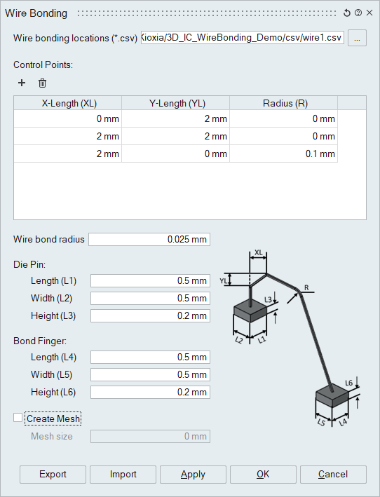
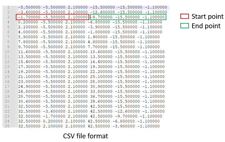
Wire bonding locations (*.csv)
Select the csv file that contains start/end points for each wire.
Control points
Use the ‘+’ button to add as many control points as needed to define the wire profile.
For each control point, specify the following parameters:
- X-Length (XL) – Horizontal distance from the previous point
- Y-Length (YL) – Vertical distance from the previous point
- Radius (R) – (Optional) Fillet radius to smooth the bend at the control point
Wire bond radius
Specify the wire radius.
Die Pin
Specify the length(L1), width(L2) and height(L3) of the die pin.
Bond Finger
Specify the length(L4), width(L5) and height(L6) of the bond finger.
Create Mesh
By default, this tool creates wires as Parasolid geometry. Use this option to automatically create the mesh (Tet4) for the wires.
Example