Use the Members tool to create members between two joints.
From the Skeleton ribbon, click the Members tool.
Figure 1.
Select a starting joint.
Select an ending joint or a symmetry plane.
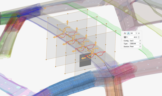
Sections are created in between the two.Figure 2. . The primary joint is selected and then the symmetry plane. The preview
shows the sections in symmetry, these can be edited as required .
Click on the guide bar to define
options.
Number of control points
The number of sections that are created throughout the symmetric
member creation.
Cut planes
The default length and width of the cut plane.
Realize member
Create 1D mesh and the associated beam sections based on the cut
plane sections.
Auto weld section
Will create an enclosed
section by stitching flanges together.
Auto detect thin solids
Is a classification
process of solid geometry to enhance the output of the member
creation.
Create sketch
Will allow full
ease-of-use edit capabilities in sketcher.
Section cleanup
Will remove overspill
areas of a section to reduce the section to only what’s desired.
The option will remove a large amount of manual
cleanup.Figure 3. Figure 3shows the current
behavior without section cleanup. The over-capture of the
section cut plane includes areas that are not desired. When the
1D mesh is created, the 1D sections include the over-capture
which would need to be cleaned up manually.Figure 4. Figure 4shows the behavior with
the section cleanup capability enabled. Despite the section cut
plane intersecting additional regions, those additional regions
are filtered out automatically resulting in a clean
output.Figure 5. In a real-world
example, the difference between the two outputs is notable. The
left side ofFigure 5is not using cleanup,
while the right side ofFigure 5is using cleanup. The
section cleanup capability will remove hours of manually
cleaning up multiple sections.
Create components across member
Will dissect the member into components.Figure 6. The left side of Figure 6
shows the default behavior, one component per member. The right side
of Figure 6
shows the multiple components created per member.
Resize and reposition the planes in the following ways:
Click and drag the boxes at the edges of the plane(s) to resize and
capture the appropriate structure.
Toggle in the microdialog to
move each plane globally. Use the drop-down menu to control which section(s)
display the manipulator.
Click in the microdialog to
align the last member created. Press Ctrl + Z to
undo.
If the member is being realized , define the 1D mesh and the associated beam
sections.
Optional: Click the Exclude selector on the guide bar then pick entities to exclude from the member if
required.
Figure 7. . The member, 1D mesh, and beam sections are created and applied
appropriately
On the guide bar, click one of the following:
- Apply and stay in the tool
- Apply and close the tool
- Exit the tool without applying
Assign Beam Sections to Members or Member Sections
Use the Assign tool if a member is created without a beam section or the beam section
needs to be changed.
From the Skeleton ribbon, Member tool group, click the
Assign tool.

 on the guide bar to define
options.
on the guide bar to define
options.


 in the microdialog to
move each plane globally. Use the drop-down menu to control which section(s)
display the manipulator.
in the microdialog to
move each plane globally. Use the drop-down menu to control which section(s)
display the manipulator. in the microdialog to
align the last member created. Press Ctrl + Z to
undo.
in the microdialog to
align the last member created. Press Ctrl + Z to
undo.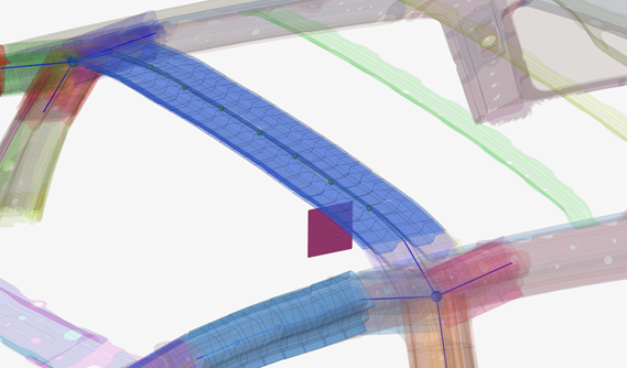
 - Apply and stay in the tool
 - Apply and close the tool
 - Exit the tool without applying