Use the Joint Box tool to define junctions in your skeleton model.
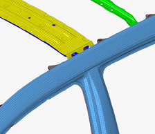
Figure 1. Original Model
From the Skeleton ribbon, click the Joint Box
tool.
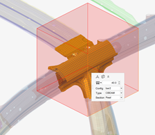
Figure 2.
Select the node or elements around which to create a bounding box.
Any elements found within the box are used for joint creation.Figure 3.
Click on the guide bar to define
options.
Create joint box
Use the box as a mechanism to select elements to generate the joint
location and legs.
Remove joint legs
Create a joint without the corresponding legs.
Mesh member joint
Automatically create 1D mesh on the joint legs and apply the beam
sections.
Auto weld section
Will create an enclosed
section by stitching flanges together.
Auto detect thin solids
Is a classification
process of solid geometry to enhance the output of the member
creation.
Create sketch
Will allow full
ease-of-use edit capabilities in sketcher.
Section cleanup
Will remove overspill
areas of a section to reduce the section to only what’s desired.
The option will remove a large amount of manual
cleanup.Figure 4. Figure 4shows the current
behavior without section cleanup. The over-capture of the
section cut plane includes areas that are not desired. When the
1D mesh is created, the 1D sections include the over-capture
which would need to be cleaned up manually.Figure 5. Figure 5shows the behavior with
the section cleanup capability enabled. Despite the section cut
plane intersecting additional regions, those additional regions
are filtered out automatically resulting in a clean
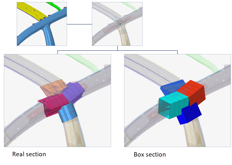
output.Figure 6. In a real-world
example, the difference between the two outputs is notable. The
left side ofFigure 6is not using cleanup,
while the right side ofFigure 6is using cleanup. The
section cleanup capability will remove hours of manually
cleaning up multiple sections.
Dimensions
Controls the length, width, and weight of the bounding box.
Use orientation and dimensions
For repeated operations, the previous box attribute information can
be used so that the box can be created the same repeatedly.
Edit the box size in the following ways:
Click in the microdialog to
move the box globally.
Click in the microdialog to
update the box's dimensions. You can click a face and drag its arrow or
entire a precise value.
Figure 7.
If the member joint is being meshed, set the parameters in the microdialog drop-down.
This automatically creates 1D mesh on the joint legs and applies the
beamsections.Figure 8.
Optional: Click the Exclude selector on the guide bar then pick entities to exclude from the joint if
required.
On the guide bar, click one of the following:
- Apply and stay in the tool
- Apply and close the tool
- Exit the tool without applying
Assign Beam Sections to Member Joints
Use the Assign tool if a member joint is created without a beam section or the beam
section needs to be changed.
From the Skeleton ribbon, Joint Box tool group, click the
Assign tool.

 on the guide bar to define
options.
on the guide bar to define
options.


 in the microdialog to
move the box globally.
in the microdialog to
move the box globally. in the microdialog to
update the box's dimensions. You can click a face and drag its arrow or
entire a precise value.
in the microdialog to
update the box's dimensions. You can click a face and drag its arrow or
entire a precise value.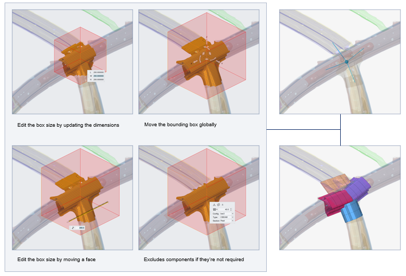
 - Apply and stay in the tool
 - Apply and close the tool
 - Exit the tool without applying