Extract Lines
Use the Extract Line tool to generate a mid-line representation from selected input, which is essential for creating reduced-order models.
When combined with the Categorize tool, the Extract Line tool can be used to streamline the reduced-order model-building process, as shown in Figure 1.
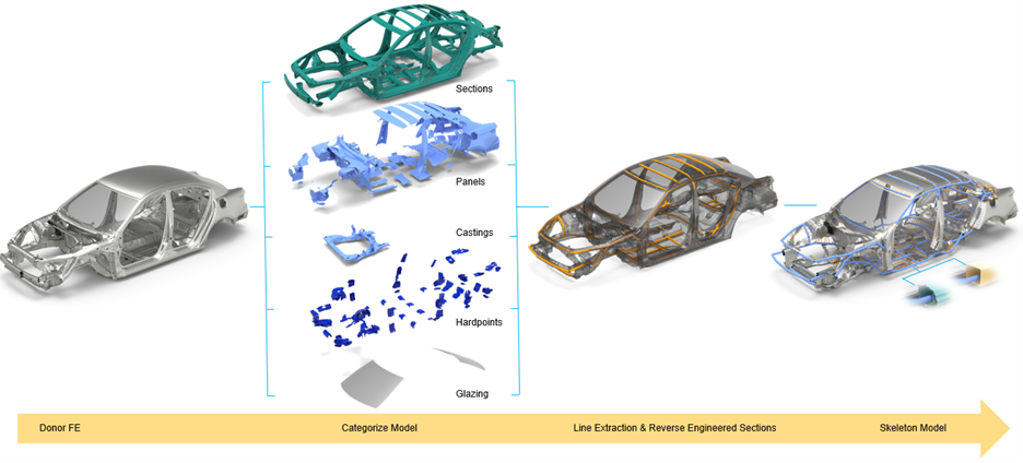
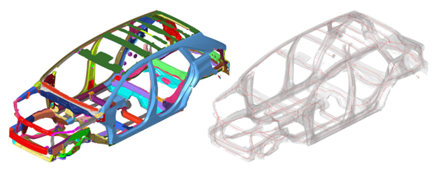
In this example, the input is the skeleton set generated by the Categorize tool. During processing, any holes in the input will be patched. Line Extract can be applied to detailed models, as demonstrated in Figure 2.
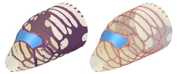
It is also valuable for interpreting both 2D and 3D topology results. For instance, Figure 3 shows how the Line Extract capability is used to extract a mid-line from a 2D topology result, which can be helpful in interpreting ribs and structural features.
Once the mid-line is generated, manual interpretation of the output may be required. Utilizing the geometry creation tools, specifically the polyline creation and sketcher, provides an efficient way to assist in interpreting the results. You can now easily create a 1D mesh and associated beam sections by utilizing the Absorb Members workflow.
-
From the Skeleton ribbon, click the Extract Line
tool.
Figure 4. 
- Select elements, components, or parts.
-
Click
 to define options.
- Fill holes
- Patches any holes in the selected input. The default is 400.
- Resolution
- Determines the level of detail. A larger value provides a broader approximation, while a smaller value gives a more refined output, though it may introduce additional noise. The default is 20.
- Branch length limit
- Removes untethered lines shorter than the specified value. The default is 60.
- Collapse threshold
- Removes any offset at junctions where two lines intersect.
- Select a symmetry plane.
-
On the guide bar, complete one of the following:
- Click
 to apply and stay in the tool.
 - Click
 to apply and close the tool.
 - Click
 to exit the tool without applying.
- Click