Morph a mesh by selecting a dimension in the model and change its values.
There are five dimensional types that can be altered: distance, angle, radius, curve
ratio, and arc angle.
For distance and angle, you define the dimensions by selecting domains, nodes and/or
handles that will be used to alter the dimension.
For radius, curve ratio, and arc angle you select one or more curved edge or 2D
domains whose radii or curvature you wish to change.
Note: The curve
ratio tool scales your radius by a factor rather than a set radius. If you want
to change a radius from 5.0 to 8.0, you need to set the curve ratio to 1.6. If
the domains that you want to morph do not have constant curvature, the curvature
tool will maintain the curvature variations while scaling the local
radii.
If you have any reflective symmetries (1-plane, 2-plane, 3-plane, and cyclical) in
the model, the changes applied to any domains assigned to those symmetries will
automatically be reflected to all linked domains.
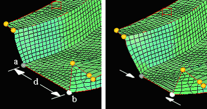
Figure 1 shows morphing
by altering a distance using two handles. Handles a and b are selected, and the
distance d between them is calculated and displays in the distance= field. By
changing this value and clicking Morph, the distance between
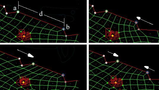
the handles can be set to a new value.Figure 1. Figure 2 shows
morphing by altering a distance using the nodes and handles option. The green circle
marks end a and the blue circle marks end b. The original distance "d" is 23. Three
handles are selected as followers for end a and two are selected as followers for
end b (upper left picture). The distance is changed to 15 and the morph button is
clicked. If hold end a is selected, the handles move in such a way such that only
node b will move to make the new distance 15 (upper right picture). You can also
choose hold end b (lower left picture) or hold center (lower right picture).
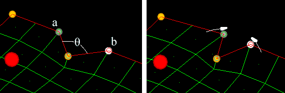
Figure 2. Figure 3 shows
morphing by altering an angle using the nodes and handles option. The green circle
marks end a, the red circle marks end b, and the blue circle marks the angle vertex
(left). The original angle "theta" is 90 degrees. One handle is selected for each
end. In this case since the handles are coincident with the nodes at end a and end
b, the two handles or edge domains options could have been used instead. The value
in the angle window is changed to 45 degrees, the hold middle option is selected,
and the morph button is clicked. The handles are moved in such a way that the new
angle between the selected nodes becomes 45 degrees. Alter angle also has the hold
end a and hold end b options.
Note: If the red and green nodes do not have coincident
follower handles, HyperMesh iterates until the angle
is either within one one-thousandth of a degree of the target or it has
converged as close as possible.
Figure 3. Radius, curvature, and arc angle allow you to select one or more edge domains
(and any associated 2D domains) and adjust their radius, curvature, or arc angle.
Radius and arc angle are intended to be used with domains of constant curvature.
Curvature is intended to be used with domains of changing curvature or with multiple
domains with different radii. Curvature will change the radius along the length of
the curve by multiplying it by the given ratio. The hold options for radius and
curvature determine whether the ends move towards or away from the center (hold
center), tangentially (fillet), stay fixed (hold ends), or move towards one end
(hold end). For the hold end option you should select all of the nodes for the held
end or ends.
Figure 4 shows morphing
by radius using the fillet option and the options by edges and auto-symmetry. The
two edge domains are selected and both have a radius of 5. The radius is changed to
3 and the morph button is clicked. The ends of the edge move tangentially to keep
the angle constant. This option is very useful for changing fillets. The radius
change of the 2D domain is not as smooth as the radius change for the edge domains.
To better change the radii of the 2D domain for this example the center calculation
method should be switched to by normals and the 2D domain should be selected along
with the two edge domains. If the result is not accurate enough, which can often be
the case when the mesh is not perfectly curved, try creating a line through the
center of curvature and using the by line option.
Note: For the by line option, the
line will only be at the center of curvature for the first morph unless you are
using the hold center option.
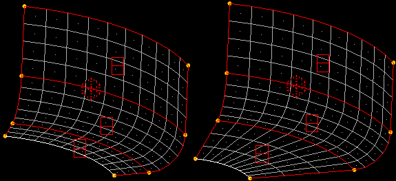
Figure 4. Figure 5 shows
morphing by radius using the hold ends option. The two edge domains are selected and
both have a radius of 5. The radius is changed to 10 and the morph button is
clicked. The ends of the edge do not move and the angle is forced to change.Figure 5. Figure 6 shows
morphing by radius using the hold center option. The edge domain is selected which
has a radius of 20. The radius is changed to 10 and the morph button is clicked. The
center of the domain does not move and the radius is changed.Figure 6. Figure 7 shows
morphing by radius using the hold end option. Two edge domains and the 2D domain are
selected with the edge domains having a radius of 5. The nodes on the lower edge of
the 2D domain are selected to mark the held end. The radius is changed to 3 and the
morph button is clicked. The domains are altered in such a way that the radius is
changed and the selected end is held.Figure 7.
From the Morph ribbon, click the arrow next to the
Morph tool set name and select Alter
Dimensions.
In the Morph: Alter Dimensions dialog, define
parameters.
Parameter
Action
Dimension
Choose the type of
dimension that you wish to alter.
Distance
Distance between two nodes.
Angle
Angle made by two nodes and a vertex.
Radius
Radius of an edge domain and associated 2D
domain.
Curve Ratio
Curvature of an edge domain and associated 2D
domain.
Arc Angle
Length of an edge domain and associated 2D
domains about an axis, as determined by
degrees.
For example, a semi-circular curved surface
would have an arc angle of 180 degrees; changing
it to 90 degrees would make the surface encompass
only a quarter-circle instead of a
half-circle.
For example, a semi-circular curved surface would have
an arc angle of 180 degrees; changing it to 90 degrees would
make the surface encompass only a quarter-circle instead of
a half-circle.
Measure
Between
Choose the type of
entities to use.
Two Handles
One handle will be end a and the other will be
end b. Once selected, the distance between them
displays in the distance = field.
When morphing by angle, this option also
requires you to select a vertex to define the
angle (in conjunction with end a and end b).
Edge Domain Ends
The handles at the ends of the selected edge
domain will be used for end a and end b and moved
toward or away from each other to change the
distance between them.
Two Nodes
End a and end b may be located at nodes other
than where handles are and that "follower" handles
for each end will be moved as groups towards or
away from each other to change the distance
between the two nodes.
Restriction: This option is only available
when morphing by distance.
Measure
Using
Choose the
orientation of the angle normal to an existing entity or direction.
Three Nodes
Use any of the global axes (x, y, or z) to morph
in a plane that is normal to that axis.
Two Edge Domains
Use the plane normal to any two other nodes
which you have selected.
Two Handles and a Vertex
Use the plane formed by end a, end b, and the
vertex node.
Restriction: This option is only available
when morphing by angle.
End A
Specify one end of
the relevant distance. Depending on the setting of the
entities to use switch, this will require you to select a
handle, node, or node a.
Restriction: Only
available when morphing by distance or
angle.
Followers (End
A)
The selected
follower handles will move as end a moves.
Restriction: Only available when morphing by
distance and measuring between two nodes or by angle and
measuring between three nodes.
End B
Specify one end of
the relevant distance or angle. Depending on the setting of
the entities to use switch, this will require you to select
a handle or node b.
Restriction: Only available
when morphing by distance and two handles or nodes and
handles, or by angle and nodes and
handles.
Followers (End
B)
The selected
follower handles will move as end b moves.
Restriction: Only available when morphing by
distance and measuring between two nodes or by angle and
measuring between three nodes.
Add to
Current
Select the
Add to Current check box to add
the value of radius = or arc angle = to the existing radius
or arc instead of replacing it.
Restriction: This
option is only available when morphing by radius or arc
angle.
Edge and
2D
Select one or more
edge and 2D domains. For every 2D domain you must select at
least one edge domain which touches it. The average radius
of the selected domains automatically appears in the radius
= input.
Restriction: Only available when
morphing by radius, curve ratio, or arc
angle.
Center
Calculation
Choose a method of
center calculation.
By Axis
Select an axis to be the center of curvature for
the selected domains.
By Edges
Use the plane of the edge domains and curvature
from node to node to calculate the center. Also,
you have the option of letting HyperMorph automatically create
a symmetry on 2D domains for which two edge
domains have been selected, which generally makes
the dimension alteration smoother across the 2D
domains if the mesh is regular.
Note: Only
available for edge domains.
By Line
Select a line to be the center of curvature for
the selected domains, then choose project normal
or project direct from the toggle. This toggle
determines the direction which the nodes will be
projected towards the line when determining the
center for each node.
By Node
Select a node to be the center of curvature for
the selected domains.
By Normals
Use the normal vectors for the elements on 2D
domains and the selected edge domains to
interpolate the center of curvature for each
node.
This method can be imprecise due the fact that
element normals do not always point exactly
towards the center of curvature.
Restriction: Only available when morphing
by radius, curve ratio, or arc angle.
Hold
Choose which
portion of the line between the selected ends remains fixed,
and therefore determines which of the two ends moves.
Restriction: For morphing by radius, curve ratio,
or arc angle:
Choose how the center of the radius is
treated with respect to movement during the
morph.
hold center
Keep the center in place, moving both ends of
the radial curve equally.
fillet
Change the radius and move the center as
necessary to keep the radial curve tangent to its
surrounding mesh.
hold ends
Keep both ends of the radial curve in place,
effectively moving its center. This means that as
the radius increases, the curve between the ends
becomes flatter.
hold end
Select the node at one end of the curve that
you wish to keep steady. The other end of the
curve and the center will move when morphed.
Force Edges
Circular
Force the selected
edge domains to be circular after morphing.
Restriction: Only available when morphing by
radius, curve ratio, or arc angle.
Force Edges
Flat
Project the nodes
of selected edge domains to a plane prior to morphing.
Restriction: Only available when morphing by
radius, curve ratio, or arc angle.