Domain entities divide the model into different domains during morphing.
Each domain contains either elements (for 1D, 2D, 3D, or general domains), a series of
nodes (for edge domains), or a group of nodes (for global domains).
The shape of a domain changes when the handles associated with a domain move, which in turn
changes the position of the nodes inside those domains.
Domains do not have an active or export state.
Domain Types
For 1D, 2D, and 3D domains, only elements of the appropriate type will be assigned to the
domain. If selected elements of the correct type are already assigned to another domain,
then they will be reassigned to the new domain.
Handles will automatically be created at the ends of the edge domains.
1D Domain
Group of 1D elements, such as bars and rigid elements.
2D Domain
Group of shell elements. When 2D domains are created, edge domains will also be
created around the edges of the elements for the domains.
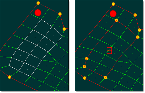
Figure 1 shows a 2D domain
that has been created from the selected elements. You only need to select the elements
that you want to be in the new domain. The elements are automatically assigned to the
new domain, edge domains are created around it, and handles are added at appropriate
positions on the edge domains. The 2D domain created allows for the creation of a bead
by moving the two handles at the ends of the edge normal to the plane of the
elements.Figure 1.
3D Domain
Group of solid elements. When 3D domains are created, 2D domains will be created on
their faces and edge domains will be created around the edges of the 2D domains.
General Domain
General domains can contain any type of element (1D, 2D, or 3D), but edges or faces
are not created along with the general domain. General domains will respect 2D and
edge domains and you may create edge domains inside general domains if you desire.
Handles will be created for general domains where the domains contact other elements
whether those elements are in domains or not. Where the general domain contacts
elements outside of domains, a handle is created at every node on the interface. Where
general domains contact elements in other domains, handles will be created at logical
locations to ensure control of the general domain. Once created, general domains can
be morphed just like any other domain, even though they may contain different element
types.
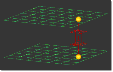
Figure 2 shows a general
domain that has been created for a connector consisting of two rigid spiders and a
hexa element. Note the four-rectangle shaped icon (in the center) for the general
domain. Two handles have been manually added at either end of the domain so that the
domain can be morphed as needed. Moving either handle will cause the entire domain to
stretch evenly across its length. Figure 2.
Note: It is possible to include the shell elements as part of the general domain
in addition to the hexa and rigid elements.
Edge Domain
Series of nodes that are commonly found along the edges of 2D and 3D domains. You
are not able to create edge domains that are not attached to any 2D, 3D, or general
domains.
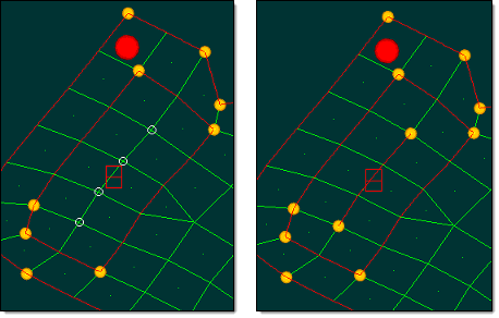
Figure 3 shows an edge domain
that has been created for the selected nodes. The nodes should be selected in order
following the path of the edge domain without skipping over any nodes. HyperMesh automatically adds handles at the ends of the edge
domain at points along the length where the angle and curvature direction change above
the set threshold. The edge domain created allows for the creation of a bead by moving
the two handles at the ends of the edge normal to the plane of the elements.Figure 3.
Global Domain
Group of nodes.
You may create more than one global domain in a model, but no node may belong to
more than one global domain. Global handles only affect the nodes assigned to their
global domain.
If you only need to change the shape of your model in a general way, then you only
need to create a global domain. For large models, automatically generating local
domains for the full model, such as using the generate auto function, is time
consuming and possibly unnecessary. If you only need to change a part of the model,
then you only need to create domains for that part.
When creating a global domain, you have the option of having global handles
automatically generated for you. HyperMesh will place
these handles at the eight corners of a box surrounding the model and at areas of peak
nodal density within the model.
Create Domains
Create morphing domains.
From the Morph ribbon, click the arrow next to the
Morph tool set name and select
Domains.
In the Morph Domains dialog, select
Create for Action.
Define the domain.
Option
Action
Type
Select the type of
domain to be created.
1D Domains, 2D Domains, and 3D Domains
Select a group of elements, or choose all
elements. Then select the check box options,
described individually.
Connector Domains
Select connectors to create domains, and select
the method (independent, main, secondary, general,
and cluster) in which handles are created and
managed for the domain. This option allows you to
create connector domains that behave the same as
1D domains, as in many cases the two are the same.
Independent connector domains can be
controlled individually.
Secondary connector domains are dependent on
main domains.
Main connector domains control the behavior of
secondary domains.
Cluster connector domains are controlled
together.
Note: For the main and secondary options,
both 1D and connector domains are treated the same
way in terms of interacting with 2D
domains.
In addition, select whether or not to retain
handles.
Edge Domains
Select a node list in order, from one end to the
other.
Note: The nodes do not have to be along the
edge of a domain, but they should follow along
element boundaries without skipping
nodes.
General Domains
Select a group of elements, or choose all
elements. Then select the check box options,
described individually.
Note: General domains can
contain any type of element, therefore all
elements will include all elements in the model
(1D, 2D, and 3D).
Global Domains
Select a group of nodes, or choose all nodes;
then, select whether you want to create (global)
handles, or only the domain itself.
Global and Local Domains
Select a group of elements, or choose all
elements, Then select the check box options,
described individually.
HyperMesh will
create 1D, 2D, and 3D domains for the selected
elements according to their type and then create a
global domain governing all of the nodes of the
selected elements.
Local Domains
Select a group of elements, or choose all
elements. Then select the check box options,
described individually. HyperMesh will create 1D, 2D,
and 3D domains for the selected elements according
to their type.
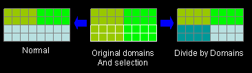
Divide by
Domain
Create multiple
new domains based on the domains that the selected elements
already belong to.Figure 4. Example: Divide by Domains. The different colors represent each domain. The different colors in
Divide by
Comps
Create new
domains, divided along component boundaries. This can be
combined with divide by domains so that one domain will be
generated for each combination of component and
domain.
Retain Handles
Keep any handles
already generated. Clear this checkbox to delete old handles
lying within the new domain when creating that
domain.
Partition 2D Domains
Divide created 2D
domains based on defined settings.
Click Create.
Edit Edges
Merge, split, or add handles to an edge domain.
From the Morph ribbon, click the arrow next to the
Morph tool set name and select
Domains.
In the Morph Domains dialog, select Edit
Edges for Action.
Define the parameters.
Option
Action
Option
Add Handles
Creating dependent handles on an edge domain
speeds radius and curvature changes for the given
edge. This is useful for radius changes on edge
domains attached to domains that contain a large
number of nodes.
Merge
The ends of the edge domains must meet at common
nodes.
Split
The selected node must be on the given edge but
cannot be on the end of the edge.
Domain
When splitting a
domain, use this collector to select the domain to
split.
When merging domains or adding handles, use
this collector to select the domains to merge or add
handles to.
At Node
When splitting a
domain, use this collector to select the node at which you
wish the split to occur. The node selected when splitting
edges must be on the given edge, but cannot be on the end of
the edge.
Retain Handles
Do not delete the
existing handles when the handles are recalculated.
Click Split.
Organize Domains
Combine domains and add or remove nodes and elements from domains.
Only the elements of the appropriate type for the domain will be organized. The model
is automatically updated, and new edge domains and handles may be created after the
elements are organized.
From the Morph ribbon, click the arrow next to the
Morph tool set name and select
Domains.
In the Morph Domains dialog, select
Organize for Action.
Define the parameters.
Option
Action
Option
Select the type of
function to perform.
Options:
Add Nodes/Elems
Combine Domains
Remove Nodes/Elems
Domain
Type
Choose the type of
domain. You can add/remove elems to local domains, or nodes
to global domains.
Restriction: Only available
when Option is set to Add
Nodes/Elems or Remove
Nodes/Elems.
Select
When Option is set
to Add Nodes/Elems, select the domain
to which you wish to add nodes or elements.
When Option is
set to Combine Domains, select
the domains you wish to combine.
Nodes
Add or remove
nodes to/from global domains.
Restriction: Only
available when Option is set to Add
Nodes/Elems or Remove
Nodes/Elems.
Retain Handles
Keep any handles
already generated. Clear this check box to delete old
handles lying within the specified domain.
Restriction: Only available when Option is set to
Combine
Domains.
From the Morph ribbon, click the arrow next to the
Morph tool set name and select
Domains.
In the Morph Domains dialog, select
Update for Action.
Select a function to perform.
Function
Action
Delete All
Delete all
domains, and/or all morph entities, throughout the
model.
Partition
Partitions 2D
domains by dividing them along element edges where the angle
between the elements exceeds the domain angle parameter or
where the curvature changes from flat to positive or
negative. The curve tolerance parameter is used to determine
whether two elements are flat or curved. Curvature changes
are ignored if the partitioning order parameter is set to
"angle-based."
Remesh
Place the new
elements into the domains of the old elements, and
optionally allow you to preserve your saved shapes.
If you
remesh a 3D domain and have the new mesh type set to
quads, the 2D domains on the surface of the 3D domain
will be remeshed with quad elements. The inside of the
3D domain will be remeshed with a layer of pyramid
elements (one quad face with four tria faces) with the
rest of the inside remeshed with tetra
elements.
Note: For elements outside of domains where
shells and solid elements are touching, remeshing
may destroy the connectivity between the solid and
shell elements. Covering the solid elements with a
layer of shell elements will prevent this from
happening.
If the mesh is too
distorted, such as when element angles exceed 175
degrees, it may not be possible to remesh the elements
or domains. In those cases you can smooth the elements
or domains before remeshing, morph your mesh in several
steps while remeshing after each one, or morph the mesh
to fix poor elements.
Figure 5.
Reparameterize
Reparameterize
domains if they have been edited. This keeps the handle
influences updated and thus, in most cases, you will not
need to reparameterize your domains
manually.
Reparameterizing affects the way that
handles influence the nodes. If a domain is morphed a
great deal, the handles may not influence the nodes in
the way you might expect. For instance, if a node is
moved from one side of the mesh to the other, it will
still be influenced more heavily by the handles it was
previously close to rather than by the handles it is
currently near. If this happens, you may want to
reparameterize the domain so that the handles close to
the nodes will influence them more than the handles
farther away from the nodes. Since reparameterizing can
change shapes saved as handles, you will be asked
whether you want to preserve those shapes as node
perturbations. If you click yes the shape will be
converted to node perturbations and remain essentially
unchanged. If you click no the shape will still apply to
handles, which will affect the model in a different way
than before, thus changing the shape. Shapes saved as
node perturbations are unaffected by
reparameterization.
Set Colors
Define the
color.
Smooth
Mesh
Apply smoothing to
the selected domains as a morph, which means that it can be
undone and redone and will be saved as part of any
shape.
The kriging method of smoothing applies only to
elements inside domains. If you wish to apply smoothing
to elements outside of domains while using the kriging
method for elements inside domains, choose one of the
options which lists both the kriging method and another
method, such as kriging + auto, which will perform
kriging style smoothing on elements inside the domains
and autodecide style smoothing on elements outside the
domains.
The squish corrected method of smoothing
allows you to select which nodes are fixed in place
during the smoothing process. When smoothing domains,
the handle nodes will automatically be fixed, but you
may optionally select the nodes on edge domains and face
domains to be fixed as well as any nodes that lie on
feature edges. You can also manually select any other
nodes to remain fixed. When smoothing elements, no nodes
will automatically be fixed, and you have the same
options of which nodes to fix automatically.
The
squish corrected method also allows you to select
whether to pursue the best element quality, the best
smoothing speed, or a balance between the
two.
Subdivide
3D
Subdivide 3D
domains into several 3D domains depending on the shape of
the 3D domain and the number of divisible 2D domains.
When
subdividing, a 2D domain will not be divided unless it
is specified as being a divisible domain. Thus, the
original face domains will be preserved.
The
maximum number of new domains is equal to the number of
indivisible domains. In cases where a 3D element touches
more than one indivisible 2D domain there may be fewer
3D domains created than the maximum. There can be cases
where the 3D domain cannot be subdivided if an
insufficient number of divisible 2D domains have been
selected.
Update 1D/
Connector Method
Determine how
handles are placed for the 1D and connector domain, and how
the dependencies are assigned.
Based on the defined function, select or define the following options:
Option
Defined Function
Action
Divide by
Comps
Partition
Create new
domains, divided along component boundaries. This can be
combined with divide by domains so that one domain will be
generated for each combination of component and
domain.
Divide by
Domain
Partition
Create multiple
new domains based on the domains that the selected elements
already belong to.Figure 6. Example: Divide by Domains. The different colors represent each domain.
Divisible 2D
Domains
Subdivide 3D
Select the 2D
domains that you wish to divide.
When subdividing, a 2D
domain will not be divided unless it is specified as
being a divisible domain. Thus, the original face
domains will be preserved.
Select
Domains
All
Select the domains
that you wish to divide, for which you wish to update the
1D/connector domain method, that you wish partition, or that
you wish to reparameterize.
Selected 3D domains will be
subdivided into several 3D domains depending on the
shape of the 3D domain and the number of divisible 2D
domains.
The 1D/conn method determines how handles
are placed for the 1D and connector domain and how the
dependencies are assigned. See the parameters subpanel
for an explanation of the different methods.
Select
Entities
Remesh 2D/3D
Choose either
Domains or Elements.
If you choose elements, you should
only select elements that are not inside domains, since
doing so would remove those elements from their domains
when they are remeshed.
Elem Size
Remesh 2D/3D
Specify the
desired element size.
Note: Available when
Remesh is selected for Edge
Options.
Select
1D/Connector Domain Method
1D Conn Method
Options:
Independent, Secondary, Main, Cluster
Choose how handles
are placed for the 1D and connector domain and how the
dependencies are assigned.
Iterations
Smooth Mesh
Specify a limit on
the number of iterations when smoothing the mesh.
New Mesh
Type
Remesh 2D/3D
Choose the type of
mesh to use during remeshing.
Preserve
Shape
Remesh 2D/3D
Preserve morphing
shapes after the remesh. Otherwise, shapes may be
lost.
Retain
Handles
Subdivide 3D
Partition
Do not delete the
existing handles when the handles are recalculated.
Size
Control
Remesh 2D/3D
Attempt to keep
elements roughly similar in size during meshing.
Skew
Control
Remesh 2D/3D
Avoid producing
highly-skewed elements during meshing.
Smooth
Method
Smooth Mesh
Auto Decide
Select the best method.
Size Corrected
Create elements of roughly uniform size.
Shape Corrected
Create elements of roughly uniform shape.
Angle Corrected
Create elements of roughly uniform angle.
QI Optimized
Create elements that conform to preset element
Quality Index criteria.
Kriging
Applies only to elements inside domains.
Kriging+Auto
Select the best method while using kriging
algorithms.
Kriging+Size
Create elements of roughly uniform size while
using kriging algorithms.
Kriging+Shape
Create elements of roughly uniform shape while
using kriging algorithms.
Kriging+Angle
Create elements of roughly uniform angle while
using kriging algorithms.
Kriging+QIOpt
Create elements that conform to preset element
Quality Index criteria while using kriging
algorithms.
Squish Corrected
Improve the element squish quality index of the
selected domains or elements.