Morphing Preferences

Define morphing preferences.

Open morphing preferences and define the following preferences by completing one of the following options:
  • From the File menu, select Preferences > HyperMesh > Morphing.
  • From the Morph ribbon, click the Options tool.


    Figure 1.

Morphing

Option Action
Use symmetry links Create links between symmetric handles active or inactive for all symmetries.

When not selected, morphing the model behaves differently. Reflective symmetries (1-plane, 2-plane, 3-plane, and cyclical) are completely ignored, while non-reflective symmetries no longer link handles but still affect node influences. Select Use symmetry links to reactivate them for subsequent morphs in which you need symmetry.

Use constraints Turn your constraints on and off without changing their active status.

If selected, constraints will not be applied to the model while morphing.

If selected, only the active constraints will be applied during morphing. This allows you to perform some morphing options without using any constraints, and then reactivate the constraints for further morphing.

Elements mid-nodes Choose a method for handling second order element mid-nodes.
No correction
Leave mid-nodes at the positions where the morphing operations placed them.
For example, when mapping a mesh to a surface, the mid-nodes will be placed on the surface during the mapping. Selecting this option will leave them there.
Force midpoint
Reposition the mid-nodes at the exact midpoint of the element edges after any morphing operation.
Hold current
Reposition the mid-nodes by averaging the perturbations of the nodes at the ends of the element edge, and apply them to the mid-nodes instead of using the perturbations calculated for the mid-nodes during the morphing operation. This method will generally hold the current positions of the mid-nodes relative to the ends.
Curve edge domains
Use the hold current method to determine the mid-node positions, but only for nodes on edge domains.
Curve 2D domains
Use the hold current method to determine the mid-node positions, but only for nodes on edge and 2D domains.
Minimum step size (distance) Specify the minimum step size (in model units) used during interactive morphing. All morphing applied using interactive methods, such as using a manipulator, dragging a handle along a vector, or dragging a handle across a surface, will be rounded to the nearest multiple of the minimum step size before being applied to the handles. Thus, setting the minimum step size distance to 1.0 will force the handle to be morphed in steps no less than 1.0, such as 2.0, 3.0, 6.0 and so on. These steps will be reflected in the movement of the handles across the screen, which will occur in discrete increments.
Minimum step size (angle) Set the minimum step size (in degrees) for interactive morphing.
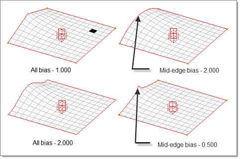
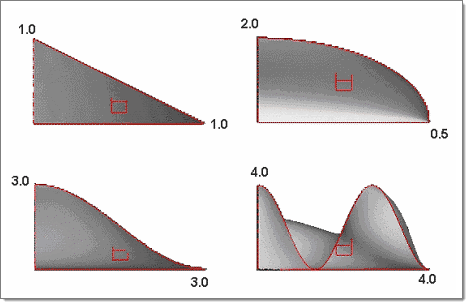
Handle bias style
Exponential
Use a straightforward exponential function (higher bias results in more influence).


Figure 2.
Sinusoidal
Determine node movements using a sine-cosine function. The exact effect varies depending on the bias value chosen for a handle.
  • If the bias is less than 1.0, sinusoidal biasing functions just like exponential biasing.
  • For bias values from 1.0 and 2.0, the circular or elliptical complement is calculated. When used at a value of 0.5 in conjunction with a neighboring handle with a bias factor of 0.5, the resulting curvature is perfectly circular or elliptical depending on the morph. For values below 2.0 a linear distribution is mixed in which will be completely linear for a value of 1.0.
  • For bias values higher than 2.0, a bias value of 3.0 between neighboring handles yields one-half cycle of a sine function. A bias value of 4.0 yields one-and-a-half cycles of a sine function. Each additional 1.0 added to the bias at either end adds another cycle to the sine function. Bias values that are fractions will follow the curvature of the next highest whole number in terms of cycles and will be mixed with a linear component which is more pronounced as the bias value gets lower (for example, a bias factor of 3.1 is an almost linear mixture of a bias of 4.0 and 1.0).


Figure 3.

Auto QA

Option Action
Element quality check Evaluate element quality after every morphing operation, including the application of constraints when they are created.
Auto smoothing Choose the type of smoothing applied after morphing.
Off
Disable auto-smoothing.
Autoselect
Calculate the lengths of all of the elements' edges to find the extreme values. If the ratio of smallest to largest is below a certain threshold, it uses the shape correcting algorithm; otherwise, it uses the size correcting algorithm.
Size corrected
Moderate variations in element edge size through the mesh using a modified Laplacian over-relaxation that correctly handles mixtures of quad and tria elements.
Shape corrected
Moderate variations in element aspect ratio through the mesh using a modified isoparametric-centroidal over-relaxation that correctly handles mixtures of quad and tria elements.
Angle corrected
Globally minimize the average deviation of element angles from their ideal values.
QI optimized
Optimize as many facets of elements quality (size, angle, Jacobian) as you desire. If you click edit criteria it will bring up the element quality calculator which you can use to set the quality criteria used during smoothing.
Note: The QI optimized algorithm only applies to shell elements.
Unsquish (fast, even, best)
Optimize the element squish value of tetra and pyramid elements, the jacobian value of penta and hexa elements, and the skew value of tria and quad elements. When using it you may choose between three options: fast, even, and best. The fast option will smooth the elements as fast as possible using a relatively low quality benchmark. The best option will smooth the elements using a relatively high quality benchmark but will take more time to solve. The even option will smooth the elements while balancing your desire for good quality elements and fast solving speed.
Note: Smoothing in real time can be slow for large meshes.
Auto remeshing Select when remeshing after morphing occurs. For both manual and on release remeshing, select the mesh type (quads, trias, mixed, or r-trias), the target element size, and whether you want size control, skew control, to preserve shapes, and whether or not to also remesh 3D elements.
For automatic remeshing on release, there is a text box labeled qa fail% >. This value represents the percentage of affected elements that have to fail the auto quality check before remeshing is triggered.
Note: Automatic remeshing will not be active unless automatic quality check is turned on, as the automatic quality check is used to supply the current qa fail%.
During automatic remeshing (which is active when you select the on release option), watch carefully as new messages are written to the screen after morphing. After highlighting the elements which failed the auto qa, if the number of failed elements exceeds the qa fail %, you will see the message, "QA - right click to remesh," instead of simply, "QA" written either next to your cursor or in the bottom-right corner of the window. If you right-click, all affected domains and elements will be remeshed. If you left-click, remeshing will not occur. Once the remesh is complete, you will see the message, "remesh - right click to reject." This is your only chance to reject the remeshing that has been performed. If you right-click, the remeshing will be rejected and the morphing will be retained. If you left-click, the remeshing cannot be undone, although the morphing can be.
Note: An affected element is any element that touches a node that has been morphed, whether or not it has failed QA. An affected domain is any domain that contains an affected element.

Connectors, Clusters, Equations

Option Action
Morphing mode Choose how connectors, cluster domains, and equations are treated.
Use doms/mvols
Treat cluster domains as rigid bodies, meaning that any morphing which affects at least one node on any cluster will be averaged and applied to all nodes in the cluster. All connectors and equations will be allowed to be stretched by morph volumes and domains.
All as clusters
Treat all connectors, cluster domains, and equations as rigid bodies, meaning that any morphing which affects at least one node on any cluster will be averaged and applied to all nodes in the cluster.
Note: The morphing of clusters will affect all elements touching the clusters whether they were moved or not.
All stretchable
Treat all connectors as stretchable, meaning that nodes on the interior of the connector may perturb due to the influences of the nodes on the exterior. Unlike clusters, the morphing of stretchable connectors will not affect the elements touching the connectors. Only the connectors and cluster domains are affected. All equations and cluster domains will be treated as rigid bodies, meaning that any morphing which affects at least one node on any cluster will be averaged and applied to all nodes in the cluster.
Morph by type
Treat rigid type connectors, such as spotwelds and bolts, cluster domains, and equations as rigid bodies, meaning that any morphing which affects at least one node on any cluster will be averaged and applied to all nodes in the cluster. Flexible type connectors, such as seams and area connectors, will be treated as stretchable.
Fix equations
Treat all cluster domains and equations as rigid bodies, meaning that any morphing which affects at least one node on any cluster will be averaged and applied to all nodes in the cluster. All connectors will be allowed to be stretched by morph volumes and domains.
Free equations
Treat all cluster domains and rigid type connectors as rigid bodies, meaning that any morphing which affects at least one node on any cluster will be averaged and applied to all nodes in the cluster. All equations and flexible type connectors will be allowed to be stretched by morph volumes and domains.
Rotation mode Choose the rotation applied to any connectors or equations treated as clusters, or to cluster domains.
none
Do not apply rotation to any clusters.
tilt
Rotate planar clusters to match the movement of the surrounding mesh but only in out-of-plane directions. Clusters whose nodes do not lie in a plane will undergo full rotation.
spin
Rotate planar clusters to match the movement of the surrounding mesh but only in-plane. Clusters whose nodes do not lie in a plane will undergo full rotation.
full
Rotate all clusters in all planes to match the movement of the surrounding mesh.
Stretch mesh around connectors, clusters, and equations Ensure that the surrounding mesh transitions smoothly when clusters are morphed.
Note: Due to the rigid body movement of clusters, morphing performed on a mesh connected to one end of a cluster will move that cluster and affect unmorphed meshes connected to the cluster. If mesh stretching is active, morphing will be applied to the unmorphed meshes as well.

Parameters

Option Action
Global influences Choose whether global domains and morph volumes will affect nodes within them directly, hierarchically, or by a mixed method.
Mixed method
The hierarchical method will apply for all the nodes in local domains and the direct method will apply to all other nodes.
Direct
Global handles directly affect each node.
Note: Straight edges in the mesh may become curved and circular holes can become warped while morphing with the direct method.
Hierarchical
Global handles affect the local handles whose nodes lie in the global domain or are registered to a morph volume, and they in turn affect the nodes within their domains.
Note: This method preserves straight edges and circular holes since their shapes are governed by the local domains and handles.
Nodes outside of local domains are unaffected by global handles, which may result in mesh distortion between elements that are inside local domains and elements that are not. This problem can be alleviated by using the mixed method.
Choose the method of calculating influences for global domains.
Spatial
The fastest method for generating global influences based on a spatial formulation for the entire model.
Kriging
Use the kriging algorithm to solve for the perturbations of the nodes affected by the perturbation of global handles. This algorithm generally gives the best results of the three in terms of element quality but can be slow for large number of nodes and handles. A practical upper limit on the number of handles you should have in a global domain when using kriging is 3000. Computers with above average memory and CPU available may be able to support a larger number of handles comfortably.
Geometric
Can be slow for large models or large numbers (30-plus) of global handles, but may produce more desirable influences.
Save morph list with file Save any morphs on the undo/redo list in the model file along with the morphs that have been applied to the model. When the model is reloaded, the undo/redo list will be restored and you will be able to undo and redo the morphs on the list in the same way that you could when you saved the file. If the model was saved with morphs already applied to the model, you will be able to undo them after reloading the model to get back to the original shape.

Domain Solvers

Option Action
Large domain morphing Choose when to perform the morphing of large domains.
Manual
Recommended for models with very large domains. It allows you to morph the edges of a large 2D domain, or the edges and faces of a large 3D domain rapidly, as you do not need to wait for the Large Domain Solver to run. Once you have morphed the edges and faces of your model as desired, you can then run the Large Domain Solver, which may take several minutes depending on the size of your domain.
On release
Morph the large domains after every morphing operation. During interactive morphing the large domains will only be morphed when you release the mouse button.
This is the default setting and will handle large domains in a manner similar to smaller domains for all cases except during interactive morphing.
Real time
Perform large domain morphing after every morphing operation and during interactive morphing as well.
This provides a constant display of the morphing results, but can result in slow performance.
If elements become folded during morphing, choose how to trigger the automatic unfolding and optimization step. Unfolding can be compute-intensive depending on the number off elements involved.
Ask to unfold
A prompt will ask if you want to unfold or not, once per finalized morph only if the mesh if folded.
Never unfold
Will never apply unfolding.
Always unfold
Will always apply unfolding.
Small domain solver Choose how the morphing of small domains is performed.
Standard
Use the influence coefficients between handles and nodes when morphing any domain which has fewer than the number of elements to qualify it as a large domain. Morphing of the small domains will occur automatically.
Kriging
Use the kriging algorithm to determine the morphing of the interior of small domains. Influence coefficients will be used to determine the morphing of the edge domains, but for the interiors of 2D, 3D and general domains the kriging solver will be used.
Linear static
Use OptiStruct to solve the small domains. The analysis type will be enforced displacements using the edges (and faces) of the morphed domain as boundaries and solving for the positions of the inner nodes.
Nonlinear explicit
Use Radioss to solve the small domains. The analysis type will be enforced displacements using the edges (and faces) of the morphed domain as boundaries and solving for the positions of the inner nodes.
Note: Non-linear analysis will give good results for even the most extreme morphing conditions, such as when the mesh is highly distorted, but can be very time consuming to perform.

For standard or kriging methods you may set autofix squashed domains to either off, on release, or real time. When set to on release or real time, this option will automatically try to unfold any domains which get folded during morphing. When set to on release, the unfolding operation will occur after each morphing operation is applied but not during interactive morphing. When set to real time, the unfolding operation will occur after each morphing operation is applied as well as during interactive morphing.

For either linear static or nonlinear explicit morphing, additional options are available.
Morphing mode
Choose when to perform the morphing of small domains.
Manual
Recommended for small domains that take more than a short time to solve. It allows you to morph the edges of a 2D domain, or the edges and faces of a 3-D domain rapidly, as you do not need to wait for the FEA solver to run. Once you have morphed the edges and faces of your model as desired you can then run the FEA solver, which may take several minutes depending on the size of your domain.
On release
Morph the small domains after every morphing operation. During interactive morphing, the small domains will only be morphed when you release the mouse button.
Real time
Perform small domain morphing after every morphing operation and during interactive morphing as well. This provides a constant display of the morphing results, but can result in slow performance.
Maximum size
Set for the domains which you would like to have solved using an FEA method.
Property mode
Select if you have created properties and materials for the mesh which are appropriate for the analysis type and want to use them, otherwise select automatic.
Kriging Choose when kriging is performed for domains and morph volumes.
Off
Do not use kriging for solving domains or morph volumes.
Manual
Manually control kriging.
Note:
  • The nodes influenced by the handles will not move while manual kriging is active.
  • Kriging is not a linear algorithm and thus kriging results for the movement of two handles will not be the same as adding the results for moving one handle and then the other. Manual kriging can be used to perform all of your kriging at once if you desire, even if you need to use several operations to perturb your handles.
Automatic
Perform kriging after every morph.
For either manual or automatic kriging, you will need to select additional options.
Global domains
Use kriging to solve global domains instead of the geometric or spatial methods.
Note: A practical upper limit on the number of handles you can have in a global domain when using kriging is 3000. Computers with above average memory and CPU available may be able to support a larger number of handles comfortably.
Local domains
Use kriging to solve local domains instead of the small or large domain solvers.
Note: A practical upper limit on the number of edge nodes you can have around a 2D domain or the number of face nodes you can have around a 3D domain when using kriging is 3000. Computers with above average memory and CPU available may be able to support a larger number of edge or face nodes comfortably.
Morph volumes
Use kriging to solve node perturbations inside morph volumes instead of the standard method.
Note: The algorithms differ and using kriging for morph volumes does not guarantee that the nodes registered to a morph volume will stay inside that morph volume regardless of how the corner and edge nodes are perturbed.
Drift
The global trend of the interpolation.
The values of no drift, constant, linear, quadratic, and cubic give progressively more precise interpolations while trigonometric uses a unique interpolation approach.
Covariance
The local variations of the interpolation around the drift. The values h, h^2log(h), and h^3 give progressively more precise interpolations while exp(-1/x) will give an approximate interpolation.
Nugget
Control how close the interpolated surface will fit relative to the control points. If the nugget is off or set to zero, the interpolated surface will pass through all the control points. If the nugget is on and non-zero, the interpolated surface will not necessarily pass through all the control points. The larger the nugget value is the farther away the interpolated surface is allowed to be from the control points.

FEA Results

Option Action
FEA results Choose the frequency of the results display.
Manual
Solve for and display FEA results manually.
On release
Solve for and display FEA results after every morphing operation.
Real time
Solve for and display FEA results after every morphing operation.
Off
Turn interactive FEA results off.
If the on release or real time options are selected, model FEA results will be displayed after any morphing is performed. Upon displaying the results, HyperMorph will wait until you have clicked the mouse or move the mouse into or out of the display window before continuing. If you have automated QA turned on the FEA results will be displayed after the QA results have been displayed.
Note: In order to use interactive FEA results, you must set up your model with all the necessary cards to do an analysis for one of the following types: Linear Static, Nonlinear Explicit, Stamping 1-step, or Stamping incremental. HyperMorph will not alter your model in any way in order to solve it. HyperMorph will simply write out a data file with the prefix "morphfea" and invoke the specified solver. Errors during the solution process can be found in output files located in the current working directory.
Plot Choose between contour plot and assign plot when displaying the FEA results.
Maximum plot value Used when displaying the results.

Select whether to let the software determine the maximum result, or specify the maximum result that is relevant to your task.

Minimum plot value Used when displaying the results.

Select whether to let the software determine the minimum result, or specify the minimum result that is relevant to your task.

Plot value Used when displaying the results.

Select whether to display the total magnitude or the X, Y, Z components of the results.

Mesh color Used when displaying the results.

Select the color that the results mesh is drawn.

Min/Max titles Used when displaying the results.

Display text/number titles for the minimum and maximum results in the modeling window.

Info title Used when displaying the results.

Display an informational title in the modeling window.

FEA solver Set the solver used for FEA results.
Linear Static and Stamping 1-step solvers
Solve and display the results in HyperMesh.
Nonlinear Explicit and Stamping incremental solvers
Only solve for the results.
To display the results you will need to use another tool such as HyperView Player.