Proximity Morph
Use the Proximity tool to morph mesh using a simple distance or perturbation value around selected nodes, faces, edges, or shapes.
Move the mesh using the graphical manipulator, or by optionally mapping to target entities. Usage of this tool is analogous to the Free Morph tool, but without the need to define anchors or morph areas, making it a simpler and faster approach for applicable use cases. This approach is also great for morphing surfaces of 3d meshes where only a few element layers around the moving nodes need to be morphed.
-
From the Morph ribbon, click the Proximity tool.
Figure 1. 
- Optional:
On the guide bar, click
 to define morphing options.
- Select the node(s), face(s), edge(s), or shape(s) to move.
-
Review the proximity-based morph area around the moving entities (red colored
mesh), and use the microdialog to adjust it as
needed.
Figure 2. 
-
Morph the mesh in the following ways:
- When selecting nodes, faces, or edges: Move entities freely using the
Move tool (see manipulator options below).
- The position of the Move tool is set at the center of the selected entities. Selecting new entities updates the position of the Move tool. Double-click the Move tool to reposition it manually.
- The position of the normal offset arrow is set at the center of the selected entities. Click anywhere on the selected entities to reposition the offset arrow to that location.
- When selecting shapes: Move entities freely along the selected shape
using the shape magnitude arrow. The magnitude is in the form of a
multiplying factor with respect to the selected shape.
- The position of the shape magnitude arrow is set at the center of the selected shape. Click anywhere on the selected shape to reposition the offset arrow to that location
- Activate the Targets selector and select target
geometry or mesh to map to, then use the microdialog
to execute the morph and adjust available mapping options.
Deselect targets to move nodes freely again.
- When selecting nodes, faces, or edges: Move entities freely using the
Move tool (see manipulator options below).
- Optional:
Use the Additional Anchors option on the guide bar to optionally select additional nodes to
anchor.
Anchored nodes will not move while morphing
Manipulator Options
Use the following microdialog options to change the Move tool mode between translating & rotating (default), or offsetting normal to mesh.
 - Switch to normal offset mode
- Click this button to replace the standard Move tool with a single normal offset arrow. Drag or click on the arrow to type a normal offset value to move the mesh. This mode is not available for nodes connected to 3D elements.
 - Switch to move mode
- Click this button to replace the normal offset arrow with the Move tool. The Move tool includes all standard translating and rotating arrows.
Mapping Options
Use the following microdialog options when selecting target geometry with the Proximity tool.
 - Projection
direction
- Projection
direction-
- Along vector
- Project along a user-defined direction using the Vector tool. After a direction is defined, press Esc to close the tool.
- Normal to target
- Project normal to target.
- Normal to source
- Project normal to nodes' mesh.
- Smoothed normals
- Calculate the average normal direction for all elements and then smooth them so that transitions near corners are not abrupt.
- CFD normals
- Use a sophisticated algorithm to smooth the normals for all the elements such that the elements will not get folded when their nodes are morphed.
- Fit to line
- Fit along line through target.
 - Toggle
extended surface edges
- Toggle
extended surface edges- Extend the edges of the surfaces or mesh in a direction perpendicular to the normal at the closest point on the surfaces or mesh. If this option is selected, the moving nodes will be projected on to an extended representation of the surfaces or mesh, enabling you to project nodes beyond the edge of the surfaces or mesh as well as within any holes. If this option is not selected, the moving nodes will be projected on to the interior or edges of the surfaces or mesh, which may end up distorting the morphed mesh.
- In Figure 3, three surfaces are floating above an angled mesh.
All of the nodes of the mesh are selected as moving nodes and they are
projected to the surfaces in the normal to geom direction. With extend
surface edges selected, the moving nodes are moved either to the
surfaces or to virtual surfaces which extend perpendicular to the normal
direction at the edge of the surface. Note how the nodes end up placed
inside the hole in the center of the largest surface. Without extend
surface edges selected, the moving nodes are moved to the nearest point
of the surfaces. Note how several layers of moving nodes end up
compressed at the edge of the surfaces and around the edge of the
hole.
Figure 3. 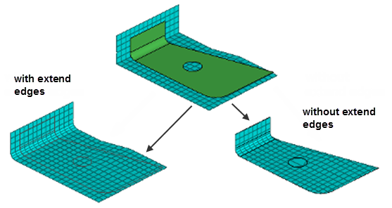
Note: Available when elements or surfaces are the target entity.  - Offset
-
- Offset distance
- Apply an offset value to be maintained between the moving
nodes and the selected targets. This value represents an
absolute distance, regardless of the direction in which the
nodes are moved.
A positive value for the offset will place the nodes short of the target, a negative value for the offset will place the nodes beyond the target, and an offset of zero will place the nodes on the target.
When mapping to target elements, the direction of the offset will be calculated using the element normals.
- Average thickness plus offset
- The offset value is automatically calculated based on the
thickness values assigned to the moving and target mesh, as follows:
Where,
t1 - Thickness of the elements connected to the moving nodes.
t2 - Thickness of the target elements. If the selected targets do not have a thickness, t2 is considered as zero.
- Average thickness times offset
- The offset value is automatically calculated based on the
thickness values assigned to the moving and target mesh, as follows:
Where,
t1 - Thickness of the elements connected to the moving nodes.
t2 - Thickness of the target elements. If the selected targets do not have a thickness, t2 is considered as zero.
 - Offset in
all directions
- Offset in
all directions- Measure the offset from each node to the closest point on the target,
regardless of projection direction.
When turned off, the offset is measured along the direction of projection of each node.