Map nodes, domains, morph volume edges, or morph volume faces in your model to a
line, node list, plane, surfaces, elements, or an equation using edge domains and handles to
guide the process.
Map a mesh to section lines, apply the difference between two lines or two surfaces
to a mesh, offset a mesh in the normal direction, and map (or create) a mesh to a
surface interpolated from a set of nodes or lines.
From the Morph ribbon, click the arrow next to the
Morph tool set name and select Map To
Geometry.
In the Morph: Map to Geometry dialog, define
parameters.
Parameter
Action
Action
Select the type of
mapping operation that you wish to perform.
Interpolate Surface
Map the selected entities (or an automatically
generated mesh) to a surface interpolated from
nodes or lines.
Line Difference
Map the selected entities from one line to
another. The entities to be mapped do not need to
lie on the line. The relative positions of the
entities to the first line are maintained when
mapping to the second.
Map To Elements
Map the selected entities to the elements
specified in a standard elems collector.
Map To Equation
Map the selected entities to a function. This
option enables the (at location switch) and the
F(xyz) (function type switch), as well as several
alphanumeric boxes to accept functions. Additional
buttons allow you to flip to the prev or next
pages of function boxes for large numbers of
functions.
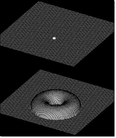
In Figure 1, the mesh for a flat plate is
mapped to an equation defining a torus centered at
the selected node. The mesh nodes were projected
normally to the plate to preserve the uniform
spacing. Figure 1.
Map To Lines
Map the selected entities to a chosen line.
Map To Node List
Map the selected entities to a specified node
list.
Map To Plane
Map the selected entities to a plane, specified
via a standard plane and vector selector.
Map To Surfaces
Map the selected entities to the surfaces
specified in a standard surfs collector.
Map To Sections
Map the selected entities to the lines of one or
more section cuts. This reveals the lines / line
list toggle and follower nodes selector.
Normal Offset
Offset the selected entities in the positive
normal direction of specified domains, by a
specified amount.
Surface Difference
Map the selected entities from one surface to
another. The entities to be mapped do not need to
lie on the surface. The relative positions of the
nodes to the first surface are maintained when
mapping to the second.
Extend
Edges
Select the Extend
Edges check box to extend the edges of the surfaces or mesh
in a direction perpendicular to the normal at the closest
point on the surfaces or mesh. If this check box is
selected, the mapped nodes will be projected on to an
extended representation of the surfaces or mesh, allowing
you to project nodes beyond the edge of the surfaces or mesh
as well as within any holes. If this check box is not
selected, the mapped nodes will be projected on to the
interior or edges of the surfaces or mesh.
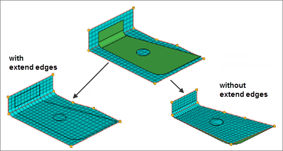
Figure 2 shows three surfaces that float
above an angled mesh divided into two 2D domains. Both
domains are selected to be mapped to the surfaces in the
normal to geom direction. With extend edges selected,
the nodes of the domains are moved either to the
surfaces or to virtual surfaces which are extended
perpendicular to the normal direction at the edge of the
surface. Notice how the nodes end up placed inside the
hole in the center of the largest surface. Without
extend edges selected, the nodes of the domains are
moved to the nearest point on the surfaces. Notice that
whenever you map nodes and elements which are part of
domains, the handles are mapped first, expanding or
compressing the surrounding mesh, which helps to reduce
mesh distortion. In this case it succeeded in reducing
mesh distortion around the edges of the surfaces, but
not around the hole.Figure 2.
Restriction: Only available when
Map to Elements or Map to Surfaces is selected for
Action.
To
Select the
starting line or node for your mapping.
Restriction: Only available when Line Difference
is selected for Action.
From
Select the
starting line or node for your mapping.
Restriction: Only available when Line Difference
is selected for Action.
Mapping
Style
Select the To
Lines or From Lines To Lines. In the Select field, below,
select the destination lines.
Restriction: Only
available when Map to Sections is selected for
Action.
Select
Select the
elements you wish to move.
Restriction: Only
available when Map to Elements is selected for
Action.
Select the line(s) you wish you map
to.
Restriction: Only available when Map
to Lines or Map to Sections is selected for
Action.
Specify the nodes that you wish
to serve as the mapping target.
Restriction: Only available when mapping by any direct method
(Map to Lines, Map to Node List, Map to Plane, Map
to Surfaces, Map to Elements, or Map to Equation)
and Node List is selected for Map
Entities.
Select the domains you wish to
move.
Restriction: Only available when
mapping by any direct method (Map to Lines, Map to
Node List, Map to Plane, Map to Surfaces, Map to
Elements, or Map to Equation) and Domains is
selected for Map Entities.
Map
Entities
Choose between map
domains and elements.
Restriction: Only available
when Map to Sections or Normal Offset is selected for
Action.
Choose between domains and nodes.
Restriction: Only available when Line
Difference or Surface Difference is selected for
Action.
Mapped
Specify the morph
volume edges that you wish to serve as the mapping
target.
Restriction: Only available when
mapping by any direct method (Map to Lines, Map to Node
List, Map to Plane, Map to Surfaces, Map to Elements, or
Map to Equation) and Morph Volume Edges is selected for
Map Entities.
Add
Followers
Select the
Add Followers check box to use
followers. Follower edges mimic the shape change of the
mapped edges.
You can also change the number of handles
on follower edges via the handle placement toggle, if
desired.
Restriction: Only available when
mapping by any direct method (Map to Lines, Map to Node
List, Map to Plane, Map to Surfaces, Map to Elements, or
Map to Equation) and Morph Volume Edges is selected for
Map Entities.
Origin
Choose the start
point for the function.
At (0,0,0)
Start the function at the default global
coordinate system's origin (0,0,0).
At Node
Select a node to serve as the starting
point.
At System
Select a local coordinate system. Its origin
serves as the starting point.
Restriction: Only available when Map to
Equation is selected for Action.
Autofill
Options
This field
displays a number of preset functions and function groups
that you can choose from based on geometry. When you pick an
option, such as hyperboloid 2, the relevant math function(s)
automatically fill in the equation field. You can modify
these equations, or type in your own.
The equation may
contain x, y, and z variables with the rest being
numbers or expressions. If using the selector to obtain
a function for a standard shape, you should replace
constants a, b, c, r, and R with numbers. The surface
defined when the function is set to zero will be used as
the target surface for the mapping.
Restriction: Only available when Map to Equation
is selected for Action.
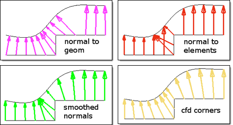
Normal
Method
When mapping along
a normal offset, choose how the normal direction is
determined.
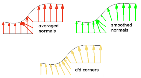
Averaged Normals
Define the normal direction for each node as the
average of only the elements touching the
node.
Smoothed Normals
Calculate the average normal direction for all
elements and then smooth them so that transitions
near corners are not abrupt.
CFD Corners
Use a sophisticated algorithm to smooth the
normals for all the elements such that the
elements will not get folded when their nodes are
morphed.
Figure 3 shows how the mesh is projected to a
curved surface using each available option. For cases where
your mesh contains sharp corners, the CFD corners option
will produce the smoothest projections. However, it can be
time consuming, and for meshes without such sharp corners
the smoothed normals option will work quickly while giving
good results. For a gently flowing mesh, the averaged
normals option can also give a smooth final mesh.Figure 3. Example: Calculate Using Methods
Restriction: Only available when Normal
Offset is selected for Action.
Calculate Normals
Using
Choose to use
either all elements when calculating the normal direction or
to use only the elements being mapped.
Restriction: Only available when Normal Offset is
selected for Action.
Target
Entities
Choose between
nodes or lines, and select the nodes or lines through which
the surface will be interpolated.
If you selected lines,
specify the number of nodes per line. The larger the
number of nodes per line, the more accurate the mapping
will be.
As a general rule, select no more than
3000 target nodes, as the surface interpolation
algorithm will use a large amount of memory and CPU
time.
Restriction: Only available when
Interpolate Surface is selected for
Action.
Map
Entities
Choose what you
wish to map to the target entities.
Domains
Map morphing domains to the target.
Morph Volume Edges
Map one or more morph volume edges to the
target. Edges may come from multiple volumes.
Node List
Map a collection of specified nodes to the
target.
Restriction: Only available when mapping by
any direct method (Map to Lines, Map to Node List, Map
to Plane, Map to Surfaces, Map to Elements, or Map to
Equation).
Choose what actually gets mapped to
the section lines. In either case, you must select the
domains or elements that you wish to map to the section
lines.
Restriction: Only available when
Map to Sections is selected for
Action.
Choose what gets
mapped to the section lines. In either case, you must
select the domains or nodes that you wish to map using
the line difference.
Restriction: Only
available when Line Difference is selected for
Action.
Followers
Follower nodes are
not mapped to the sections, but follow the basic morphing of
nodes that are mapped.
Restriction: Only
available when Map to Sections is selected for
Action.
Select:
Domains
When mapping
domains, select the domains you wish to move.
Blend %
When the map type
is interpolate surf, also input the blend %, which is how
much of the difference between the selected entities and the
interpolated surface will be applied to the mesh. At 100%,
the entities will be placed on the interpolated surface. At
50% the entities will be placed halfway between the
interpolated surface and their initial positions.
Interpolation
Shape
Choose the method
by which a surface will be interpolated.
Cylindrical
Used for interpolations which run about an axis.
Select an axis that runs through the center of
your target nodes.
Cylindrical About Nodes and Cylindrical About
Line
Used for interpolations which run around a node
list or line. Select a node list or line which
runs through the center line of your target
nodes.
Ellipsoid
Used for interpolations which enclose a roughly
elliptical volume. Select the global system, a
local system, or a center node (which uses the
global system axes) to orientate the
ellipsoid.
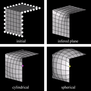
Infer Plane
Used for roughly planar interpolations. The
plane normal is approximated so that the plane
will pass through (or close to) the target nodes
or lines.
Planar
Used for roughly planar interpolations, but you
may select the orientation of the planar "starting
position."
Spherical
Used for interpolations which enclose a roughly
spherical volume. Select a node in the center of
your target nodes.
Tube About Nodes and Tube About Line
Used for interpolations which run around a node
list or line and have a closed end. Select a node
list or line which runs through the center line of
your target nodes.
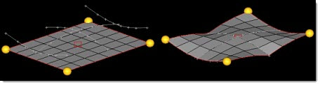
Figure 4 shows a mesh that has been morphed to
match a surface interpolated from the nodes around its
perimeter. The effects of the different shapes for the form
of the interpolation can be seen clearly with the shapes
ending up looking more like the form of the interpolation
selected in each case. However, in all the cases, the
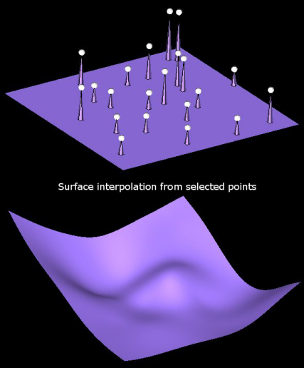
interpolated surface fits through the control points.Figure 4. Figure 5 shows how a mesh can be morphed to a
smooth interpolated surface given a handful of target
points. The basic form was an inferred plane and the Kriging
parameters used were: linear drift, h^3 covariance, and no
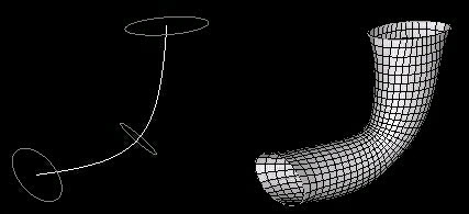
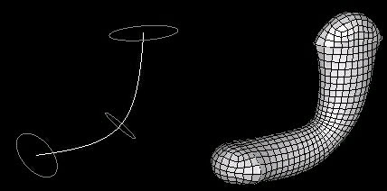
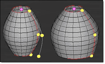
nugget.Figure 5. Figure 6 and Figure 7 show a mesh created on a surface
interpolated from a series of cross sections along a line
using the cylindrical about line method (Figure 6) and the tube about line method (Figure 7). Notice the smooth transitions between
the varying sections.Figure 6. Figure 7.
Restriction: Only available when
Interpolate Surface is selected for
Action.
Projection
Choose the
direction of mapping.
Along Vector
Map nodes to the selected geometry in the
direction specified by the vector.
Normal to Elements
Map nodes to the selected geometry in a
direction normal to the elements on which the
nodes lie, which may be a different direction for
each node.
Normal to Elements (Smoothed)
Map nodes to the selected geometry in a
direction normal to the elements on which the
nodes lie, which may be a different direction for
each node. This option will smooth the normals,
averaging the directions between neighboring
nodes, which may give more even results and reduce
mesh distortion for meshes with sharp corners.
Note: Available when mapping to a plane, surfaces,
elements, or an equation.
Normal to Elements (CFD Corners)
Map nodes to the selected geometry in a
direction normal to the elements on which the
nodes lie, which may be a different direction for
each node. This option uses the CFD corners method
to calculate the normal direction, which will give
more even results and reduce mesh distortion for
meshes with sharp corners. This option is only
available when mapping to a plane, surfaces,
elements, or an equation.
Normal to Geometry
Map nodes to the selected geometry in a
direction normal to the geometry (which could be a
different direction for each node).
In Figure 8 the mesh (viewed in profile) is
projected to a curved surface using each available option.
The fit to target option is ideal for mapping an edge or 2D
domain to a line or surface. It will stretch or shrink the
mesh to fit the target geometry, distributing the interior
nodes evenly, while the other options simply project the
nodes on to the target (or to the closest edge of the
target) in the chosen direction. The normal to geom option
works well for most mapping cases but will occasionally
fold, bind, or stretch the mesh. For cases where your mesh
contains sharp corners and you wish to use the mesh to
determine the projection direction, the CFD corners option
will produce the smoothest projections. However, it can be
time consuming, and for meshes without such sharp corners
the smoothed normals option will work quickly while giving
good results. For a gently flowing mesh, the normal to
elements option can also give a smooth final mesh.Figure 8.
Restriction: Only available when the
following actions are selected:
Map to Lines
Map to Node List
Map to Plane
Map to Elements
Map to Equations
Choose what type of entity or feature guides the
mapping process.
The first four methods of linear mapping
differ in how the nodes are projected towards the
section lines, which determines how each line influences
the nearby mesh. With linear mapping the entities are
mapped directly.Figure 9.
About Axis
Apply mapping 360 degrees around the model's
center axis, effectively changing its radius to
match the mapping.
Recommended for nonlinear situations and
cylindrical or sphere-like models, such as
bulb-shaped housing.Figure 10.
By Line Axis
Establish a straight line running through each
section line and project nodes to the section line
normal to that line.
By Line Normal
Establish a plane for each section line and
project nodes normal to the plane.
Recommended method for section mapping.
By Plane
Establish a straight line running through each
section line and find the vector which is normal
to that vector which lies in the specified plane.
Nodes are projected to each section line along
that vector.
The normal direction for the specified plane
should be aligned with the mesh, meaning that if
the mesh and the section lines lie generally in
the xy-plane, the axis for the plane should be in
the z-direction.
Recommended for section mapping where the
section lines do not lie in similar planes and
also cross each other.
By Vector
Project nodes to the section lines along the
specified vector. Select the vector to lie in the
plane of the mesh and normal to the section
lines.
Recommended for section mapping where the
section lines do not lie in similar planes and run
generally in the same direction.
Kriging
Use the kriging algorithm to fit the mesh to
the section lines. The kriging method yields
smoother results, but may not match the section
lines precisely.
Restriction: Only available when Map to
Sections or Line Difference is selected for
Action.
Specify an axis to map around
or a vector to map along. Either option presents a
standard plane and vector selector, though the resulting
vector is used differently.
Restriction: Only
available when Surface Difference is selected for
Action.
Mishandles
Choose between
keeping the current number and arrangement of handles on the
morph volume edges, or specifying a different number (up to
5 handles) for each morphed edge.
Restriction: Only available when mapping by any direct method (Map
to Lines, Map to Node List, Map to Plane, Map to
Surfaces, Map to Elements, or Map to Equation) and Morph
Volume Edges is selected for Map
Entities.
Covariance
Covariance is the
local variations of the interpolation around the drift. The
values h, h^2log(h), and h^3 give progressively more precise
interpolations, while exp(-1/x) will give an approximate
interpolation.
Restriction: Only available
when Interpolate Surface is selected for
Action.
Drift
Drift is the
global trend of the interpolation. The values of no drift,
constant, linear, quadratic, and cubic give progressively
more precise interpolations while trigonometric uses a
unique interpolation approach.
Restriction: Only
available when Interpolate Surface is selected for
Action.
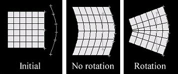
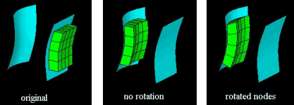
Rotate
Nodes
When mapping nodes
from a straight line to a curve, select the
Rotate Nodes check box if you
wish the curvature of the new line to affect the whole
mesh.Figure 11. Line Difference with Rotate Nodes Figure 12. Surface Difference with Rotate Nodes
Restriction: Only available when Line
Difference or Surface Difference is selected for
Action.
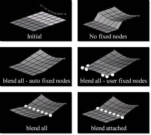
Blending
Select the type of
blending that you want between the mapped sections and the
fixed nodes.
All Elements
Blend all unfixed nodes in the model based on
the distance between the sections and the fixed
nodes.
Note: Blending will affect
unattached elements and elements which lie beyond
the fixed nodes.
Attached Elements
Blend only the nodes which lie on elements
between the sections and the fixed nodes.
Unattached elements or elements which lie beyond
the fixed nodes are unaffected.
None
Functions like having no fixed nodes except that
you may fix nodes in the mapped region without any
blending occurring.
Figure 13.
Restriction: Only available when Normal
Offset is selected for Action.
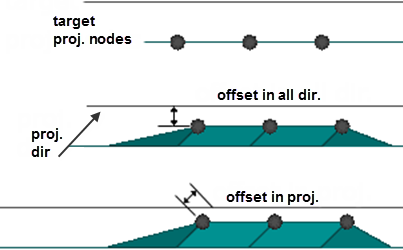
Offset
Method
Absolute Distance
Measure the offset from each node to the closest
point on the target.
Along Projection Direction
Measure the offset from each node to the target
along the direction of projection.
In Figure 14, three nodes are being offset from a
plane along a vector which is at a forty-five degree angle
to the plane normal. When Absolute Distance is selected, the
offset is measured from each node to the closest point on
the target plane, in this case along the plane normal. When
Along Projection Direction is selected, the offset is
measured from each node to the plane along the projection
vector. Notice that when using the Along Projection
Direction option, the nodes can end up closer to the nearest
point on the target than the value of the offset.Figure 14. Example: Offset in All Dir. and Offset in
Proj.
Restriction: Only available when the
following actions are selected:
Map to Lines
Map to Node List
Map to Plane
Map to Surfaces
Offset
Specify how far
the nodes will be offset from the target. Although the
mapped nodes will be moved in the specified projection
direction, the offset will be the absolute distance, in
model units, the mapped entities will end up from the target
regardless of the direction in which they were moved.
A
positive value for the offset will place the nodes short
of the target, a negative value for the offset will
place the nodes beyond the target, and an offset of zero
will place the nodes on the target.
When mapping
along a normal offset, the offset distance is how far
the selected elements are moved from their present
positions in their normal directions.
A positive
value will offset the elements in the direction of the
element normal and a negative value will offset the
elements opposite the direction of the element
normal.
Restriction: Only available when
the following actions are selected:
Map to Lines
Map to Node List
Map to Plane
Map to Surfaces
Map to Elements
Map to Equation
Constrain
Nodes
Create a new morph
constraint for the mapped nodes. The selected nodes will be
constrained to the chosen entities during subsequent morphs.
Moving
Bias
Higher values
result in nodes between the mapped nodes and fixed nodes
following the mapped nodes more closely.
Restriction: Only available when Line Difference
or Surface Difference is selected for
Action.
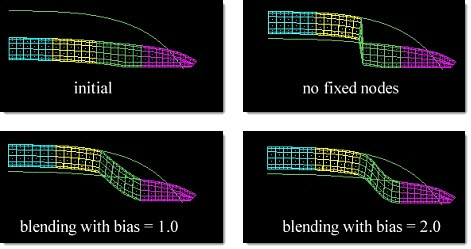
Fixed Bias
Higher values
result in nodes between the mapped nodes and fixed nodes
staying closer to fixed nodes.
Figure 15 shows the cyan and yellow components
are mapped to the line, first with no fixed nodes, then
with both the moving bias and fixed bias set to 1.0 and
the magenta component fixed, then with both the moving
bias and fixed bias set to 2.0 and the magenta component
fixed. The nodes in the transition region are nearly
linear when both bias factors are set to 1.0 and follow
a gentle curvature when both bias factors are set to
2.0.Figure 15.
Restriction: Only available when
Line Difference or Surface Difference is selected for
Action.
Nugget
Nugget controls
how close the interpolated surface will fit relative to the
control points. If nugget is not selected or the value is
set to zero, the interpolated surface will pass through all
the control points. If nugget is selected and the value is
not zero, the interpolated surface will not necessarily pass
through all the control points. The larger the nugget value
is, the farther away the interpolated surface is allowed to
be from the control points.
Restriction: Only
available when Interpolate Surface is selected for
Action.