Sculpt Mesh
Mold a mesh with a variety of virtual tools, such as creating hemispherical divots, cone-shaped projections, or molding sections with feature lines.
Areas of the mesh can be pushed or pulled to reshape it, creating either indentations or projections on the mesh.
Tool shapes include ball, cone, cylinder, node list, line, plane, surface, and mesh. Use different tools to simplify the creation of different types of deformation. For example, use the ball along a node list or line list to create a curved channel with a rounded bottom and ends, but use the cone to create a channel with a V-shaped bottom. Similarly, the ball can create a hemispherical divot or protrusion, while the cone can create a conical pit or spike. The following images illustrate use of the "ball" tool to create a raised ridge along a node list.
- From the Morph ribbon, click the arrow next to the Morph tool set name and select Sculpting.
-
In the Morph: Sculpting dialog, define parameters.
Parameter Action Sculpting Tool Choose the basic shape that will be used for sculpting. When sculpting with a cylinder or plane, a new (unlabeled) plane and vector selector displays under the tool label. Use this (including a base node) to define the cylinder's axis, or the plane tool itself.
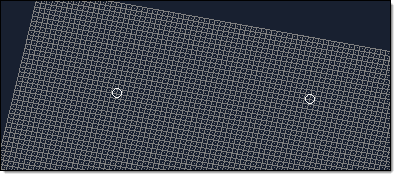
Figure 3. Ball 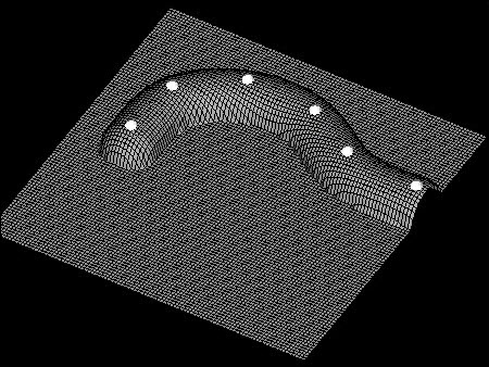
In Figure 3, the ball tool has been applied to a node list.
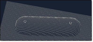
Figure 4. Cone 
In Figure 4, the cone tool has been applied to a node list with an offset. The tip of the cone is moved along the node list, which, if the node list was selected along the mesh to be sculpted, will not result in any morphing. Use an offset to push the cone past the surface of the mesh as shown in the example.
Figure 5. Cylinder 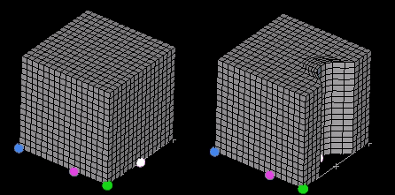
In Figure 5, a cube has been sculpted with a cylinder tool at a single point. Notice the mesh compression extending into the body of the mesh.
Figure 6. Node List 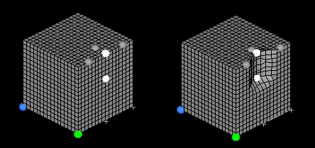
In Figure 6, a cube has been sculpting with a node list (gray circles) along a path (white circles).
Figure 7. Line 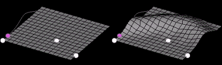
In Figure 7, a line tool is used to sculpt a mesh. Notice how the base point (purple circle) is used to locate the line relative to the path (white circles).
Figure 8. Plane 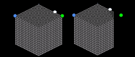
In Figure 8, a plane tool is used to sculpt a solid cube. A single node is used for the path and mesh compression of 0.5 is selected. Notice that the sculpt direction is different from the plane normal.
Figure 9. Surface 
In Figure 9, a surface is used to sculpt a mesh. A single node is used for the path (which ends up getting morphed due to the mesh compression). Notice the effect of the taper angle (45 degrees) on either side of the tool and how it prevents large mesh distortions at the tool edge.
Figure 10. Mesh 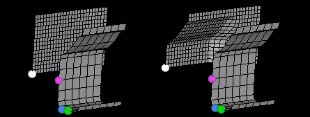
In Figure 10, a mesh tool is used to sculpt another mesh. Since the path lies on the target mesh and the base node is at the leading face of the tool, an offset was used to create the sculpting.
Radius Specify the size of the tool. Restriction: Only available for the ball and cylinder tools.Taper Angle Specify a taper angle for the tool to alter the taper of the resulting deformation. The taper of the tool is like a shroud around the tool extending opposite of the sculpt direction, at the given angle. For instance, the taper for a point is a cone. The taper helps to smooth transitions between sculpted and non-sculpted regions.
Restriction: Only available for the node list, line, surface, and mesh tools.Angle Specify the angle of the cone's taper. Restriction: Only available for the cone tools.Base Select a base node to serve as a "handle" for the tool. The base node is moved along the path and the tool moves relative to the base node. Restriction: Only available for the node list, line, surface, and mesh tools.Offset Specify the offset to determine how far the tool will be offset from the path in the move direction. Move Direction +/- Define the direction that nodes are moved when sculpted. Tool Path Choose the path along which the tool will be moved; the center of the tool follows the path. - Through Nodes
- Sculpt along a user-specified node list.
- Along lines
- Sculpt along an existing line of the model geometry.
Affected Elements Select the elements you wish to be subject to the sculpting. In this way, you can preserve parts of the mesh during sculpting (by simply not picking them). Compression - By Distance
- Set a value for the distance around the tool
where mesh compression (or expansion) is
performed. If elements are compressed by the tool,
the compression will be spread out away from the
tool but only through the specified distance. In
other words, if you set a value of 30 for the
compression distance, all the mesh compression
will occur within 30 units away from the
tool.Note: Compress by factor and compress by distance work in the same way, uniformly compressing the mesh, but they differ in what they allow you to control. Compress by factor allows you to control the amount of compression per element while compress by distance allows you to control the area within which compression takes place.
- By Factor
- Set a value between 0 and 1. The relative amount of compression (or expansion) which can be applied to the affected elements before the sculpting is "passed on" to neighboring elements.
- Full Mesh Compression
- Do not preserve the spacing between the nodes for any affected element. Elements may end up getting squashed flat.
- Use FEA linear or Use FEA Nonlinear
- Choose either auto props or user props. Select
user props if you have added properties and
materials to your model appropriate for the type
of analysis to be performed ( OptiStruct or Radioss) and want to use those
instead, otherwise select auto props. Then select
the fixed nodes for the sculpting. HyperMorph will perform an FEA
solution using either OptiStruct or Radioss to determine the
deformation of the affected elements using the
nodes affected by the tool and the fixed nodes as
enforced displacements.Note: Non-linear analysis, while more time consuming, is more appropriate for extreme mesh compression conditions and generally results in better element quality compared to linear analysis.
Figure 11. 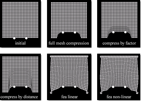
- Click Move + or Move -.