Morph Constraints
Morph constraint entities restrict or prescribe the movement of nodes during morphing, with a variety of available methods and dimensional values. These constraints are valid across all available morphing approaches and can be individually activated or deactivated at any time, even in between morphs or applying shapes.
Morph constraints do not have global active or export states in the Entity State Browser browser.
Morph Constraint Types
- Fixed
- Selected nodes do not move when the mesh morphs around them.
- Cluster
- Nodes move with the rest of the mesh, but remain fixed relative to each other. The cluster will move, but will also not stretch or become deformed.
- Smooth
- When handles move on a selected edge domain, the edge morphs according to spline-based motion rather than linear motion, creating smooth edge curves instead of straight edge lines.
- Along Vector
- Nodes will move only in the direction of a selected vector.
- Along Line
- Nodes will move, but will either move along the length of a selected line or will be bounded by the selected line.
- On Plane
- Nodes will move, but will either move across the surface of a selected plane, or be bounded by the selected plane.
- On Surface
- Nodes will move, but will either move across a selected surface, or be bounded by the selected surface.
- On Elements
- Nodes move, but will either move along the surface of a selected mesh, or be bounded by the selected mesh. This is similar to the along surface option but without requiring surface geometry.
- On Equation
- Nodes will move, but will either move across the surface of a function, or be bounded by the surface of the function. The surface of a function is defined at the threshold where f(x,y,z) is equal to zero.
- Along dofs
- Nodes will move, but can have one, two, or all three of their x, y, or z (or r, theta, or phi) coordinates fixed for any given coordinate system, local or global.
- Match Elems
- Two groups of elements will be forced to match each other regardless of
the morphing applied to the nodes on either group. The matching can be
forced relative to the normal direction of the elements, relative to a
vector, or by selecting nodes to orient one group of elements relative
to another.Note: Three or more groups of elements can be joined together by using this constraint more than once.
- Tangency
- Continuous tangency can be enforced across a pair of edge or 2D domains. Also, edge domains may have their ends constrained to defined angles, be joined in a main-secondary tangency, or have one edge "attached" to another.
- Length
- Used in conjunction with one or more morphing shapes, to enforce a specific, maximum, or minimum distance as measured along the nodes in a specified node list.
- Angle
- Used in conjunction with one or more morphing shapes, to control the angle of three selected nodes. These nodes will move, even relative to each other, but the angle they form remains either fixed, above a certain value, or below a certain value depending on your choice.
- Radius
- Used in conjunction with one or more morphing shapes, to control the radius of a given edge domain.
- Arc Angle
- Used in conjunction with one or more morphing shapes, to control the arc angle of a given edge domain. As for the radius option, the arc angle is measured using an edge domain and one of the following methods for finding the center of curvature: an axis, a line, a node, or inferred from the plane of the edge domain.
- Area
- Used in conjunction with one or more morphing shapes, to control the area of a number of elements. The selected elements will deform during morphs, but their total surface area remains either constant, above a certain value, or below a certain value, depending in your choice.
- Volume
- Used in conjunction with one or more morphing shapes, to control the volume of a number of elements. The selected elements will deform during morphs, but the volume of the selected elements remains constant, below a maximum value, or above a minimum value.
- Mass
- Used in conjunction with density data supplied by a property card, to control the mass of a number of elements. The selected elements will deform during morphs, but the total mass of the selected elements remains equal to, above, or below a specified number, even as the elements change shape during morphing.
Create Morph Constraints
Create and apply morph constraints
-
From the Morph ribbon, click the
Constraints tool.
Figure 1. 
-
On the guide bar, select the type of constraint to
create.
Available types are: Fixed, Cluster, Along, On, Smooth, Edge, Match, Length, Angle, Radius, Arc angle, Area, Volume, Mass.
-
Select nodes or domains to constrain, then use the microdialog to configure the respective constraint
options.
Some constraint types also require additional selections on the guide bar:
- Along: Select a line, vector, or direction to constrain the nodes along.
- On: Select surfaces, elements, or a plane to constrain the nodes on.
- Edge: Select the type of constraint to apply to a pair of 2D or edge domains. Options are tangent, dependent, attached, or fixed.
- Match: Make two independent element selections to match.
- Length, Angle, Radius, Arc Angle, Area, Volume, Mass: Select nodes or
domains to constrain, then, optionally, select a morph shape to apply an
allowed motion pattern in order to fulfill the dimensional constraint.
The shape definition is always required, but it can be either manually
selected or automatically generated.
These dimensional constraints are different from the rest in that they require a morph shape as additional input. Any node motions required to fulfill constraints of these types can only come from the selected shape (applied internally with a calculated scale factor), so its definition must affect the respective dimension in any magnitude when applied.
Tip: Use the Automatic checkbox under the Shape selector on the guide bar to auto-generate a Shape that affects the type of dimension. When using this option, the automatic generic shape is guaranteed to affect the given dimension, but may not match the design requirements, in which case it is possible to turn this option off and select any other custom morph shape.
- Optional:
Apply the constraint by toggling the Apply button in the
microdialog.
While this toggle is activated, constraints are calculated and applied immediately, and are recalculated automatically while further editing their definition.Note: Editing live constraints in this manner is slower due to recalculations.
Edit Morph Constraints
Edit existing morph constraint definitions or deactivate and reactivate them on demand.
-
To edit an existing morph constraint, select it in the graphics area and
either:
- Double-click
- Right-click and select Edit Morph Constraint
- From the Morph ribbon, click the
Constraints tool.
Figure 2.
Note: You can also select Morph Constraints from the Model Browser if it is more convenient, then move the mouse to the graphics area and perform any of the actions above to edit them. -
To activate and deactivate morph constraints:
- From the Model Browser, double-click on Morphing Constraints to access the morph constraints browser view.
- Use the Active column checkboxes to toggle any constraint on or off.
This applies to any subsequent morphs or morph shape applications.
Figure 3. 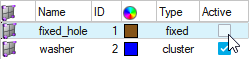
Release Morph Constraints
Remove nodes from any morph constraints.
-
From the Morph ribbon, click the
Release satellite tool.
Figure 4. 
- Select the nodes to release.
-
Click
 to remove the selected nodes from any morph
constraints they belong to.
to remove the selected nodes from any morph
constraints they belong to.