Create Gap Elements
Use the Gaps tool to create 0D/1D gap elements.
-
From the 1D ribbon, select the Gaps
0D or Gaps 1D tool.
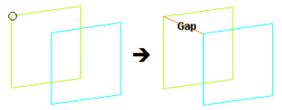
Figure 2. 
-
Define the element.
Option Action Type Select an element type. Linear 1D Create one-dimensional elements based on a projection of Elems A to Elems B. Elems A Select the elements where you want the elements to begin. Restriction: Only available when the Linear 1D check box is selected.Elems B Select the elements where you want the elements to end. Restriction: Only available when the Linear 1D check box is selected.Node A Select the element's starting node. Note: Node A is required for 0D elements.Node B Select the element's ending node. Density A-B Specify the number of gap elements you want created between each of the selected elements. Restriction: Only available when the Linear 1D check box is selected.Orientation Type Choose between methods of orienting the element. Orientation is only necessary when the nodes are coincident. - Default
- Do not use an orientation. If necessary, use the global coordinate system.
- Direction
- Select three points to define a plane whose normal serves as the vector using the N1, N2, and N3 selectors.
- Node
- Specify a node, the vector from the coincident nodes to this one is the orientation vector.
- System
- Orient the element based on a selected local system coordinate.
Property Select a property to assign to new and existing gap elements. - Click Create.
Update Gap Elements
Use the Entity Editor to update gap elements for the desired keyword.
This includes modifying the assigned nodes, property, orientation, and so on where applicable for the solver.
Note: To change the element type, see Change Element Type.