Create SPH Mesh
Use the SPH tool to define 0D Smooth Particle Hydrodynamics (SPH) mesh.
SPH is a technique used to analyze bodies that do not have high cohesive forces among themselves and undergo large deformation, such as liquids and gases.
In SPH Finite Point Method (SPH FPM), a given volume of the body of interest is discretized into particles, called SPH elements. These elements are node-like particles which have no geometric connectivity among themselves. Each SPH element has an effective mass. The summed mass of all particles in the filled volume of the body should be equal to the mass of the filled volume.
SPH elements are created to represent various materials which have high levels of deformation or are fragmented. Some examples of this are open surface fluids like the ocean, rivers, those contained within vessels, gravel or aggregate, and so on.
-
From the 1D ribbon, click the
SPH tool.
Figure 1. 
-
Define the mesh.
Option Action Entities Select the entities that define the volume to be filled with SPH elements. Use reference SPH elements are generated at the corners/face centers of the cubes which fall within the user defined criteria. Select the Use reference check box to specify which point the generation of cubes should be started.
The base point defines the starting point for cube generation, and is utilized by the mesher as a starting point.
Origin type - Global
- Uses (0, 0, 0) for the reference point.
- Local
- Define node coordinates for the reference point.
Restriction: Only available when the Use reference check box is selected.Mesh orientation Choose a method for defining the orientation of SPH elements. - Global
- Use the default global system to align generated SPH elements.
- Local
- Define reference systems local to the model orientation. Generated SPH elements are aligned using the user defined local system.
Pitch Enter the pitch. Note: Smaller numbers will result in more elements within the same space, but this will not affect the mass or density of the substance (gas, fluid, and so on) that the particles represent.Method (Pitch) Choose a method for specifying the distances between each SPH particle. - Simple cubic
- Arrange SPH particles in groups of 8, each particle being a corner of a cube.
- Face centered cubic
- Arrange the particles in groups of 14, forming the corners and the center of each face of a cube.
Mass definition Enter the mass definition. Method (Mass definition) Choose a method for specifying the quantity of fluid. - Material density
- Specify its density (the total mass is then determined by the volume filled).
- Filled volume mass
- Specify its total mass (volume and density is determined by the model volume filled).
Volume definition Choose which elements to generate SPH elements for. - All
- Generate SPH elements in all of the volumes in the model.
- Enclosed
- Generate SPH elements in the volumes enclosed by the defined nodes, and ignores the remaining volumes.
- Nth largest
- Specify which volumes to generate SPH elements in by defining the wrap size index in terms of volume size.
- Exclude enclosed
- Ignore the volume(s) enclosed by the defined nodes and generate SPH elements in the remaining volumes.
Partial fill Model a fluid or gas that does not completely fill the selected volume. Figure 2. 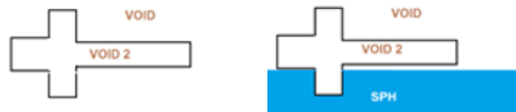
Value Specify a percentage/depth of the volume to fill. Calculation of the volume is based on the lowest point of the model, parallel to the user defined plane. Restriction: Only available when the Partial fill check box is selected.Method (Partial fill) Choose a method - Percent
- Percentage of the volume to fill.
- Depth
- Depth of the volume to fill.
Restriction: Only available when the Partial fill check box is selected.Direction Define the direction of fill, which is generally the opposite of the direction of gravity when the filled volume is installed in the real world. Restriction: Only available when the Partial fill check box is selected.Reverse direction If the particle mass is filled along the correct axis, but in the wrong direction (for example from the top of a fuel tank downward) select Reverse direction to fix this. Restriction: Only available when the Partial fill check box is selected.Wall offset Create SPH particles offset from a wall up to a distance you specify. The thickness of SPH elements is created from input. The distance between the SPH particles is driven by the pitch.
External to volume Create SPH particles outside of the defined volume. Restriction: Only available when the Wall Offset check box is selected, which enables the capability to offset SPH elements from selected volume surfaces.Wall clearance Create SPH particles from the specified distance. Tip: This is useful when trying to avoid contact of SPH elements with walls at the beginning of the solver run (first iteration) and want the solver to run smoothly. - Click Mesh.
Update SPH Elements
Use the Entity Editor to update SPH elements for the desired keyword.
This includes modifying the assigned nodes, property, and so on where applicable for the solver.