Meshing Preferences
Define meshing preferences.
From the File menu, select to define the following meshing preferences.
- Element
-
- Default Size
- Specify a default edge length for elements, in the same units that the loaded model was created in (mm, inches, and so on). This determines the default values whenever meshing, such as in the Freeform tool.
- Node Cleanup Tolerance
-
- Automatic or Manual
- For Manual, specify the tolerance used to maintain the finite element data in the model. Any two nodes are coincident if the distance between them is less than the value.
- Face Selection
-
- Mesh feature angle
- Specify the maximum distance that the selected entity must be within to be included in the selection. When entities are selected by face, attached adjacent elements are progressively selected if the feature angle between them is less than or equal to the mesh feature angle. This also affects automatic mesh cleanup.
- Advanced
-
- Beamsection default thickness
- Change the default thickness for the beamsection shell part.
- Element order
- Use first-order (corner nodes only) or second-order (corner and mid-edge nodes) elements when meshing.
- Element organization
- Select the component to place new elements in.
- CAD topology revision
- Select the method for handling your model when the
geometry's topology changes.
- Delete mesh
- Deletes the mesh from the affected surfaces.
-
Figure 1. 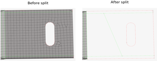
- Disassociate mesh
- Disassociates the mesh from the affected surfaces.
-
Figure 2. 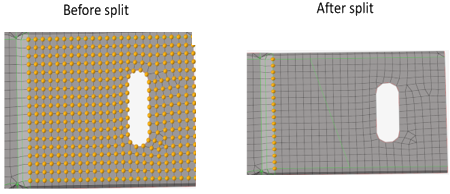
- Remesh
- Automatically remeshes the affected surfaces.
-
Figure 3. 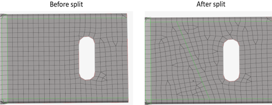
- Keep mesh along matched topology
- Skips the remesh when the geometry topology is matched with the finite element edge.
-
Figure 4. Before suppression 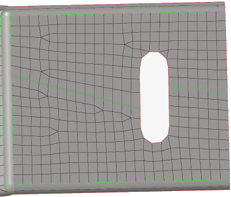
-
Figure 5. Suppressed 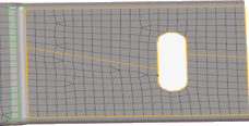
-
Figure 6. After suppression, no remesh 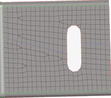
- Transformation
- Select a method to control the 2D remesh and
connectivity with the surrounding mesh on a CAD
surface transformation.
- Transformation off
- On a surface transformation, the mesh is remeshed and moves along the surface by breaking the connectivity with the surrounding mesh.
-
Figure 7. Before surface transformation 
-
Figure 8. After surface transformation 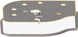
- Keep and break
- On a surface transformation, the mesh is kept in the original position without remeshing by breaking the connectivity with the surrounding mesh.
-
Figure 9. Before surface transformation 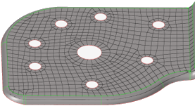
-
Figure 10. After surface transformation 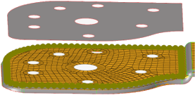
- Move and break
- On the surface transformation, the mesh moves along the surface without remeshing by breaking the connectivity with the surrounding mesh.
-
Figure 11. Before surface transformation
-
Figure 12. After surface transformation 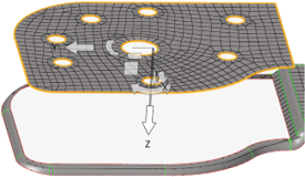
- Remesh tetra mesh
- Updates the tetra elements associated with the solid geometry locally when the geometry is modified with operations like Boolean, solid trim, or surface offset. If the boundary layer or hex elements are present, those are replaced with tets upon update.
- FE topology revision
-
- Keep mesh
- Keeps the existing mesh on the finite element topology revision.
-
Figure 13. 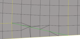
- Remesh
- Remeshes the surrounding mesh on the finite element topology revision.
-
Figure 14. 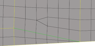
- Rebuild
- Rebuilds the surrounding mesh on the finite element topology revision.
-
Figure 15. 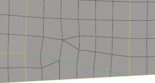
- Allow duplicate IDs
- Allows properties in different groups to have the same ID. Duplicate properties cannot exist in the same group.
- Create FE Geometry when duplicating elements
- Create FE Geometry when duplicating elements associated to geometry.
- Mixed property warning
- Displays a warning when components contain both direct and indirectly assigned properties.
- Retain loads and BCs
- Retains loads and boundary conditions that are applied to nodes when remeshing.
- Retain element values
- Retains element properties, offsets, nodal thicknesses, orientation, and 1D element values while remeshing.
- Automatically update sets to mesh changes
- When remeshing changes the model, automatically attempt to update sets accordingly.
- Allow 2D-3D set segment re-parenting
- Set segments applied to coincident 2D or 3D elements are re-parented to underlying elements if one is deleted.
Examples
When elements are moved away from surfaces:
- Case 1
- Topology changes within a surface and brings the nodes within the surface to the origin. Nodes associated to the edges remain in the current position.
- Split within the surface:
Figure 16. 
Figure 17. 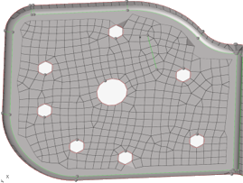
- Case 2
- Topology changes on the surface and the edges and brings the nodes associated to the surface and edges to the origin.
- Split the surface between two edges:
Figure 18. 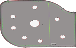
Figure 19. 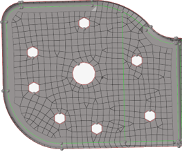
- Case 3
- Topology changes on the surface between two points and brings the nodes associated to the surface to the origin. Nodes associated to edges remain in the current position.
- Split the surface between two points:
Figure 20. 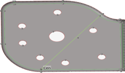
Figure 21.