Kinematics and Compliance
The K&C event simulates a vehicle mounted on a test rig where forces and displacements are applied at the tire contact patches to characterize suspension behavior.

The event can be added to a half-vehicle or a full-vehicle model and is supported by the Cars/Small Trucks, Heavy Trucks, and Two-Wheeler vehicle libraries.
Jack Constraints
When you add a K&C event, the event adds a Jack body for each Tire in the model and attaches the Tires to their corresponding jack.
The wheel jack connects to the ground by a translational joint in the global Z direction, and the Wheel Body is connected to the Jack Body by an inplane joint. The wheel body is free to move longitudinally, laterally and to rotate about any direction relative to the jack body.
Parameters
- Selectors
-
Name Description Vehicle Body Attachment used to constrain the vehicle during simulation. Steering Joint Optional attachment used to apply steering torque during steering analysis when the vehicle end is set to 'Front'. Constraint 1 and Constraint 2 Optional attachments that need to be deactivated during the K&C simulation. If resolved, these joints are deactivated at the beginning of the event.
- Simulation Modes
- TYPE - PREDEFINEDAllows you to configure a sequence of suspension analyses by selecting the type of test and specifying the end time for each. It is used to evaluate how the suspension system responds to different input conditions over time.
- Ride analysis: All wheels are subjected to a vertical
displacement input through the jacks. The inputs have the same amplitude with
left and right wheels being in phase. This part of the event lasts for
t_rideseconds:Table 1. Time in Seconds Action 0 to t_ride/4Wheels move from Design Position to Jounce Position. t_ride/4 to t_ride/2Wheels move from Jounce Position to Design Position. t_ride/2 to 3*t_ride/4Wheels move from Design to Rebound Position. 3*t_ride/4 to t_rideWheels move from Rebound Position to Design Position. t_rideRide Analysis ends. - Roll Analysis: For this part of the event all wheels
are subjected to a vertical displacement input through the jacks. The inputs
have the same amplitude with left and right wheels being out of phase. This part
of the event lasts for
t_rollseconds:Table 2. Time in Seconds Action t_previous to t_roll/4Left Wheels move from Design Position to Jounce Position. Right wheels move from Design Position to Rebound Position.
t_roll/4 to t_roll/2Left Wheels move from Jounce Position to Design Position. Right wheels move from Rebound Position to Design Position.
t_roll/2 to 3*t_roll/4Left Wheels move from Design Position to Rebound Position. Right wheels move from Design Position to Jounce Position.
3*t_roll/4 to t_rollLeft Wheels move from Rebound Position to Design Position. Right wheels move from Jounce Position to Design Position.
t_rollRoll Analysis ends. - Lateral force (Parallel/Opposed): Lateral force is applied at all contact patches in the same/opposite direction to simulate cornering conditions. The duration of the force application is defined by the user.
- Aligning moment (Parallel/Opposed): Aligning torque about the vertical axis (Global Z) is applied on all contact patches in the same/opposite direction. The duration of the torque application is defined by the user.
- Longitudinal acceleration/braking: Longitudinal force is applied at all contact patches along the negative/positive X direction of the Global Frame to simulate an acceleration/braking condition. The duration of the force application is defined by the user.
- Steering analysis: This final part of the kinematics
and compliance analysis involves testing the front suspension kinematics when a
steering input is applied. The duration of the steering input is
t_steer, and the steering motion is applied in both
directions:
Table 3. Time in Seconds Action t_previous to t_steer/2Steering motion is applied in the counter-clockwise direction. t_steer/2 to t_steerSteering motion is applied in the clockwise direction. t_steerSteering Analysis ends.
- Ride analysis: All wheels are subjected to a vertical
displacement input through the jacks. The inputs have the same amplitude with
left and right wheels being in phase. This part of the event lasts for
Axle Settings
- Suspension Travel
-
Name Description Jounce travel The vertical distance the wheels travel upward relative to the ground during suspension compression in ride analysis. Rebound travel The vertical distance the wheels travel downward relative to the ground as the suspension extends in ride analysis. Wheel travel in roll The vertical distance the wheels move both upward (jounce) and downward (rebound) relative to the ground during roll analysis. Max lateral force The lateral force applied at the wheel contact patch to represent the effect of cornering. Max longitudinal force The longitudinal force applied at the wheel contact patch to simulate braking and acceleration. Max aligning torque The torque applied about the wheel’s vertical axis. Note: The Suspension travel parameters are only used when Simulation modes are set to Predefined and define the magnitudes of the demand signals. - Axle Parameters
-
Name Description Vehicle end Choose between “Front” for Front suspension or “Rear” for rear suspension. This information is used in calculating Suspension Design Factors (SDF). Type of suspension Choose between Dependent or Independent. This information is used in calculating Suspension Design Factors (SDF). Steered axle An axle whose wheels are controlled by a steering system to guide the vehicle's path. Select Yes if this axle is steerable. Tire static loaded radius The distance from the center of the wheel hub to the ground when the tire is mounted on the vehicle and loaded. Tire vertical spring rate The stiffness of the tire, defined as the amount of vertical force required to compress the tire by a certain distance. This value should match the value specified in the tire property file when using force-based tire models. - Demand Signals
- TYPE - PREDEFINEDThis field displays the expressions used to compute wheel displacements and contact patch forces. It cannot be edited directly, as the expressions are generated automatically based on the selected simulation modes, end times, and suspension travel parameters.
- Wheel actuator motion
This field contains the expressions used during the ride and roll phases of the analysis for left and right wheels. These expressions (command variables) define the desired vertical displacements and are compared to the actual global Z-displacements of the wheel center markers, relative to their original positions (feedback variables). The difference between them is used to compute the control forces applied to the jacks (Jack Vertical Actuators), allowing them to move to the desired positions.
The expressions are explained in detail below:- Left
Figure 2. Left Wheel Demand Displacement 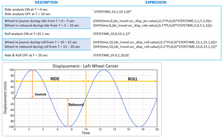
- Right
Figure 3. Right Wheel Demand Displacement 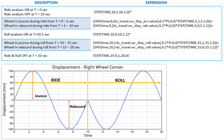
- Left
- Steering
Contains the expression for the steering phase of the analysis. This expression (command variable) defines the desired steering wheel angle and is compared to the actual angular displacement of the steering wheel, relative to its original position (feedback variable). The difference is used to calculate the control torque applied to the steering wheel to reach the target angle.
The expression is explained in detail below:Figure 4. Demand Steering Wheel Angle 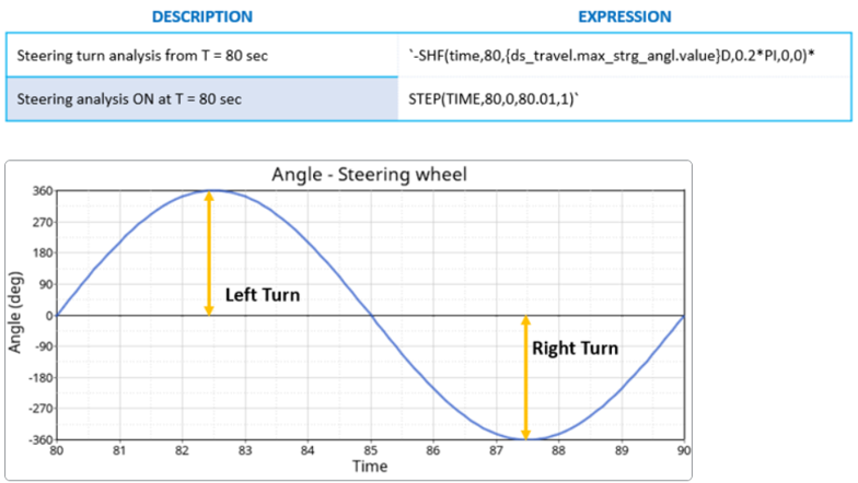
- Wheel contact patch forceThese expressions define the longitudinal, lateral and aligning forces applied at the wheels contact patch:
Force Description Fx – Left Fx – Right
`SHF(time,60.0, {ds_travel.max_long_force.value},0.1*PI,0,0)*STEP(TIME,60.0,0,60.01,1)*STEP(TIME,69.9,1,70.0,0)-SHF(time,70.0, {ds_travel.max_long_force.value},0.1*PI,0,0)*STEP(TIME,70.0,0,70.01,1)*STEP(TIME,79.9,1,80.0,0)`The expression contains a simple harmonic function that applies a sinusoidal force input, whose amplitude is defined in the Suspension Travel, at frequency of 0.1PI. For the first 10 seconds, between 60 – 70 seconds, the force is in the positive X direction and negative X for the next 10 seconds.
Fy - Left `SHF(time,20.0, ds_travel.max_lat_forc.value,0.2*PI,0,0)*STEP(TIME,20.0,0,20.01,1)*STEP(TIME,29.9,1,30.0,0)+SHF(time,30.0, ds_travel.max_lat_forc.value,0.2*PI,0,0)*STEP(TIME,30.0,0,30.01,1)*STEP(TIME,39.9,1,40.0,0)`The expression contains a simple harmonic function that applies a sinusoidal force input, whose amplitude is defined in the Suspension Travel, at a frequency of 0.2PI. The force is in the positive Y direction between 20-40 seconds.
Fy - Right `SHF(time,20.0, ds_travel.max_lat_forc.value,0.2*PI,0,0)*STEP(TIME,20.0,0,20.01,1)*STEP(TIME,29.9,1,30.0,0)-SHF(time,30.0, ds_travel.max_lat_forc.value,0.2*PI,0,0)*STEP(TIME,30.0,0,30.01,1)*STEP(TIME,39.9,1,40.0,0)`The expression contains a simple harmonic function that applies a sinusoidal force input, whose amplitude is defined in the Suspension Travel, at a frequency of 0.2PI. The force is in the positive Y direction between 20-30 seconds and in the negative Y for the next 10 seconds. This is done to simulate parallel and opposing lateral forces with respect to the left wheel.
Tz – Left `SHF(time,40.0, ds_travel.max_algn_torq.value,0.2*PI,0,0)*STEP(TIME,40.0,0,40.01,1)*STEP(TIME,49.9,1,50.0,0)+SHF(time,50.0, ds_travel.max_algn_torq.value,0.2*PI,0,0)*STEP(TIME,50.0,0,50.01,1)*STEP(TIME,59.9,1,60.0,0)`The expression contains a simple harmonic function that applies a sinusoidal torque input, whose amplitude is defined in Suspension Travel, at a frequency of 0.2PI between 40 to 60 seconds.
Tz – Right `SHF(time,40.0, ds_travel.max_algn_torq.value,0.2*PI,0,0)*STEP(TIME,40.0,0,40.01,1)*STEP(TIME,49.9,1,50.0,0)-SHF(time,50.0, ds_travel.max_algn_torq.value,0.2*PI,0,0)*STEP(TIME,50.0,0,50.01,1)*STEP(TIME,59.9,1,60.0,0)`The expression contains a simple harmonic function that applies a sinusoidal torque input, whose value is defined in Suspension Travel, at a frequency of 0.2PI between 40 to 60 seconds. For the first 10 seconds between 40 – 50 seconds, the torque is in the same direction as the left wheel and opposite to it for the next 10 seconds. This is done to simulate parallel and opposing aligning torques with respect to the left wheel.
- Wheel actuator motion
- TYPE – USER DEFINED
- When the simulation mode is set to User Defined, you can manually edit the
expression field entries in the Demand Signals.
- Wheel travel
In the Wheel travel test, you can define the desired vertical displacements (Wheel actuator motion) and the desired steering wheel angle (Steering).
- Compliance
In the Compliance test, you can define the desired steering wheel angle (Steering) and the forces/torques applied at the wheel contact patches (Wheel contact patch force).
- Wheel travel
Simulation Settings
- Analysis Parameters
- For more information see the Parameters: Simulation - Attributes topic.
- Dynamic Settings
- Defines the simulation control parameters for a time-domain-based nonlinear dynamic analysis. For more information see the Parameters: Transient Solver - Attributes topic.
- Static Settings
- Defines the solution control parameters for static and quasi-static analysis. For more information see the Parameters: Static Solver - Attributes topic.
Automated Output Report
| Report Name | Report Signals |
|---|---|
| Ride test |
|
| Roll test |
|
| Lateral force test – Parallel |
|
| Lateral force test – Opposing |
|
| Aligning torque test - Parallel |
|
| Aligning torque test - Opposing |
|
| Longitudinal braking test |
|
| Longitudinal acceleration test |
|
| Steering test (in Full Vehicle/Front K&C) |
|