Methods of Orientation
Coordinate systems in MotionView can be oriented using a variety of methods.
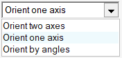
- Orient One Axis - Orient one axis explicitly using a point or a vector and allow MotionView to calculate the other two for you. This method is used to orient axisymmetric entities.
- Orient Two Axes - Orient two axes using a combination of points and/or vectors and allow MotionView to compute the third axis for you.
- Orient by Euler Angles - Orient by specifying Euler angles with respect to any other coordinate system in the model.
Orient by One Axis
The orient one axis method is used to orient axisymmetric entities. You can orient any one of the three axes of a coordinate system, and MotionView computes the remaining two.
- Select Orient one axis from the orientation method drop-down menu.
- Select an axis to orient from the axes drop-down menu.
-
Use the collector-combo box to specify the alignment method for the axis.
Figure 2. 
If you choose Point or Vector, use the collector to select the point or vector to which you want to align the axis. Point or vector coordinates are displayed beneath the point or vector label. The coordinates are protected by a lock and can be edited when the lock is green.
For a point, the axis lies on a line from the origin to the specified point. For a vector, the axis lies on a line parallel to the selected vector.
If you choose the DxDyDz alignment method, enter the global dx, dy, and dz components of the axis in the text boxes. You may also enter a mathematical expression in any of the text boxes to define dx, dy or dz.
Orient by Two Axes
The orient two axes method allows you to precisely orient any one of the three axes and approximately define either of the remaining two axes. MotionView uses a cross product to compute the direction of the third axis and calculates the precise direction of the second axis using another cross product.
- Select Orient two axes from the orientation method drop-down menu.
- Select an axis to orient from the axes drop-down menu.
-
Use the collector-combo box to specify the alignment method for the axis.
Figure 3.
If you choose the Point or Vector alignment method, use the collector to select the point or vector to which you want to align the axis. Point or vector coordinates are displayed beneath the point or vector label. The coordinates are protected by a lock and can be edited when the lock is green.
For a point, the axis lies on a line from the origin to the specified point. For a vector, the axis lies on a line parallel to the selected vector.
If you choose the DxDyDz, enter the global dx, dy, and dz components of the axis in the text boxes. You may also enter a mathematical expression in any of the text boxes to define dx, dy or dz.
- To approximate the direction of one of the remaining two axes, select a plane from the planes drop-down menu.
-
Using the collector-combo box, specify a second point or vector that is in the
direction of the second axis.
The second axis is constructed such that it aligns as closely as possible with the second point or vector. The third axis is computed using a cross product.
Orient by Angles
The orient by angles method orients a coordinate system with respect to another coordinate system using Euler’s angles. The Euler angles are entered into the text boxes and the reference coordinate system is specified with the Ref Marker collector. The three Euler angles are labeled Z, X’, and Z’’. They are used to perform a series of three simple rotations from the reference coordinate frame.
- Select Orient by angles from the orientation method drop-down menu.
- Click the Ref Marker collector and select the reference coordinate system from the modeling window, or double click the collector to open the Model Tree (from which the desired marker can be selected).
-
Double-click the ZX'Z" collector.
The Euler Angles dialog is displayed.
- Rotate the coordinate system Z degrees around the mutual Z axis.
- Rotate the coordinate system X' degrees around its new X axis.
-
Rotate the coordinate system Z" degrees around its new Z axis.
Note: To make the two coordinate systems align, enter 0, 0, 0 for the Euler angles. Your coordinate system remains parallel to the reference coordinate system as changes are made to the model.
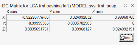
Direction Cosines
The direction cosines’ matrix is the transformation matrix that maps coordinates from the global reference frame to the current coordinate system. The three columns of the direction cosines’ matrix are unit vectors along the x, y, and z axes of the coordinate system in terms of the global frame.
Click [DC] to view the direction cosines’ matrix for a coordinate system.