
Split, Swap, Combine Elements
Use the Edit: Split tool to split quad elements and edges, combine tria elements, and swap element edges. Second order 2D and 3D elements are also supported.
-
From the Discrete ribbon, click the tool.
Figure 1. 
Elements are colored according to how well they adhere to the pre-set quality requirements defined in the criteria file. - Optional:
On the guide bar, click to
 to define the options used to
edit elements.
to define the options used to
edit elements.
-
Select an element issue type from the guide bar.
- Quality
- Checks for quality as defined in quality criteria.
- Intersections
- Checks for intersecting elements.
- Face angles
- Checks for folded or sharp angle elements.
- Optional:
Find all elements at or below a certain quality level.
- Click Find on the guide bar.
-
Increase or decrease the number of layers around patches of failed
elements by clicking
 or
or  on the guide bar.
-
Review the next or previous patch of failed elements by clicking
 or
or  on the guide bar.
-
Select a split method from the guide bar drop-down
menu.
Option Description Quality - Split an element or element edge by left-clicking.
- Swap an element edge by holding Ctrl while left-clicking on an element or edge. Additional clicks will cycle through the possible edge positions.
- Combine two tria elements by holding Shift while left-clicking on their shared edge.
Graphical Lines - Draw continuous single or multiple graphical split lines.
- Click Split.
Figure 2. 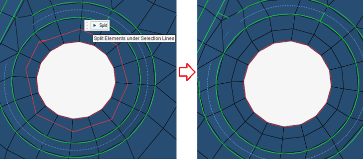
Plate - On the guide bar, click to
 to define the
options used to split elements.
to define the
options used to split elements. - Select elements to split.
- Select plate method.
- In the microdialog, divide quad elements into trias based on the advanced split
option selected.
- Shortest
- Split quad element into tria elements using the shortest possible diagonal.
- Aligned
- Align the diagonals of all the tria elements in the same direction.
- Unionjack
- Split quad elements into tria elements so their diagonals create a unionjack pattern.
- Largest angle
- Split quad elements into tria elements using the largest angle diagonal.
- Reverse the direction of the split.
- Click Split.
Figure 3. 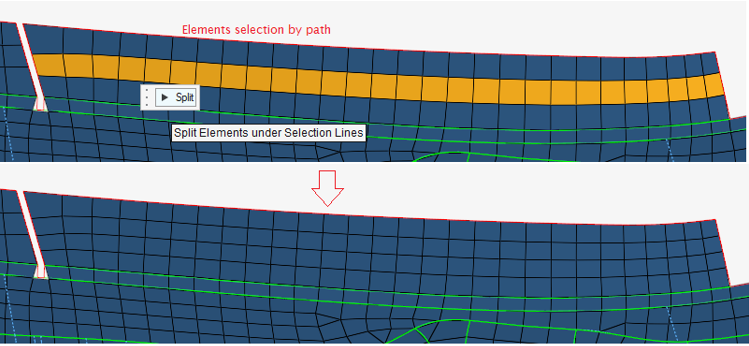
Note: When you split elements at fillets or curved faces, the middle nodes are projected back to parent edges/surfaces by default upon splitting.Figure 4. 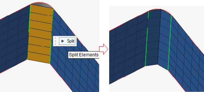
Solid - Select the elements to split.
- Select a method for splitting solid elements.
- Hexas: refine the selected hexa elements by subdividing each hexa into smaller hexa elements.
- Tetras: split selected hexa elements into the minimal number of tetra elements.
- Symmetric: split selected hexa elements into symmetric tetra sets optimized for CFD applications.
- Click Split.
All split operators work on both first and second order elements.
Layer - Select nodes to define the direction of
split/combine/delete.
Two subsequent node selections define a direction. You can select multiple node pairs simultaneously, but they should be neighboring nodes. You can use By Path in Advanced Selection to define multiple splits and works for split only.
- Select a layer method.
- Split: split hex elements along edges. You can select options for biasing while splitting layers.
- Combine: combine neighboring elements.
- Delete: delete layers of elements.
- Diagonal: split a single element along the diagonal.
- Optionally, select the Elements check box and select elements to split.
- Click
 .
.
Combine - Select the elements to split.
- Click Combine.
Tip: You can toggle graphical previews from the options menu.