Convert
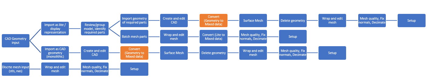
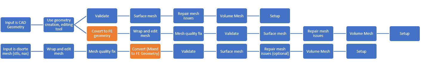
Use the Convert tool to convert entire models between data types.
In HyperMesh CFD, we have 4 defined data types. Each data type selection changes relevant tools and options, visualization toolbar options, and context menu options. These are global data types.
| Data Type | Workflow | Topology Present | Geometry modeling accessible tools | When this data type is defined | On Convert |
|---|---|---|---|---|---|
| Geometry | You can work on CAD-based topology. CAD and mesh is always associated. Can be very expensive for huge CAD models. | All time | All tools in the Geometry Repair ribbon. |
|
|
| FE Geometry | You can work on mesh-based topology using the same workflows as with Geometry data. Mesh is always referenced to topology. Lighter than CAD data but still can be slow for huge mesh topology model. | All time | All tools in the Geometry Repair and Discrete ribbons. |
|
|
| Mixed | You can either work on CAD and/or Mesh. You are free to choose to keep mesh/geometry or both, which helps for large geometry model handling. You have access to node and element-level editing. | Optional | All tools in the Geometry Repair and Discrete ribbons, with access to nodes and elements. |
|
|
| Lite | You can work on lite representation of parts. Useful for previewing huge CAD models. Comes with fast performance. |
NA |
All tools in the Discrete and Assembly ribbons. Some tools in Geometry ribbon like: Point, Line, Box, Cylinder, Revolved Region, Simplify Region are supported. |
|
|
You can convert to discrete geometry by faceting or remeshing. B-spline geometry will be removed after faceting, and all topology definitions, solids, surfaces, lines, points, IDs, and metadata will be retained. The workflow for discrete geometry will be the same as b-spline geometry. After converting the b-spline model to a discrete model, you will be able to use most tools with the same interactions.
Proper, finer sizes in tessellation will help to capture shape, and operations based on discrete geometry will be more robust.
In addition to “Geometry” and “FE Geometry” data types, a “Mixed” data type is also available. When you switch to the “Mixed” data type, you can work both on CAD and elements individually. At the time of validation, HyperMesh CFD converts the model to CAD geometry or FE geometry.
-
From the Home tools, click the Convert tool.
Figure 1. 
The Convert Model dialog opens. - Select which data type you'd like to covert to.
- If converting to FE geometry, select a method for meshing unmeshed surfaces and define the relevant parameters.
-
Click Convert.
Tessellation is performed on the entire model, so no selection is required.