Discrete Geometry

Work with discrete geometry like FE Geometry and floating elements.

The Discrete ribbon is not supported for models with CAD geometry. When you open the ribbon, you are prompted to convert to a mixed model in order to continue if your model has geometry.

"Mixed" is a third data type in addition to “Geometry” and “FE Geometry”. When you switch to the “Mixed” data type, you can work both on CAD and elements individually. At the time of validation, HyperMesh CFD converts the model to CAD geometry or FE geometry.

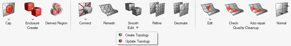
Attention: The icons shown on the ribbon below are used to complete this workflow. Click an icon to learn more about the tool.
Use the Cap tools to close openings and gaps between parts/surfaces. Use the Connect tools to trim, fuse, and stitch your discrete geometry. In CFD modeling, input parts can have topology issues, like free surfaces and self-intersections, and part assembly issues, such as parts with very close proximity and intersecting parts. Manually connecting these parts can be time consuming and require expertise in certain tools. The Enclosure tool can generate a watertight manifold model from dirty input with considerably less manual work. Use the Remesh to create new surface mesh on converted geometry. Use the Smooth tool to optimize the mesh quality of parts or surfaces. Use the Refine tool to split elements and optimize the mesh quality of parts and surfaces. Use the Decimate tool to coarsen mesh based on a defined element size. Use the Repair tool to find, review, and fix issues in the mesh. The Auto Fix tool is useful for cleaning up non-manifold edges, free edges, intersections, high aspect ratio elements, and proximity distance. Use the Edit tools to manually improve the quality of surface mesh elements and nodes. Use the Normals tool to fix element normals using different methods. Convert elements that aren't associated with geometry into FE geometry, or update existing FE geometry. Convert elements that aren't associated with geometry into FE geometry, or update existing FE geometry. Use the Derived Region tool to create enclosed and offset regions around a selection – which can be used to define volumetric refinement levels – or create projected regions in a given direction.