Cap Holes and Fill Gaps
Use the Cap tools to close openings and gaps between parts/surfaces.
The Cap tools work for tessellated geometry. If the input is b-spline geometry, first convert to discrete geometry using the Convert tool.
Cap Holes
To prepare for wrap and get a manifold model, it is good practice to close openings like pipe ends and cover unnecessary features like slots so that they are not captured in wrap results, as they are not useful for analysis. The Cap: Holes tool provides the capability to automatically or interactively create caps or patches.
-
From the Discrete ribbon, click the tool.
Figure 1. 
-
Perform automatic capping.
- Optional:
On the guide bar, click
 to define cap
options.
to define cap
options.
- Consider feature loops
- Consider both free edge loops and feature edge loops. To prepare input for wrapping, keep this option on – which closes openings to avoid leaks.
-
Figure 2. Free Edge Holes 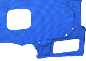
Figure 3. Free Edge Holes Filled 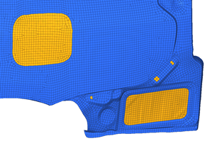
Figure 4. Feature Edge Holes 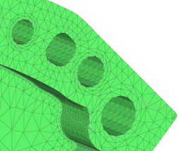
Figure 5. Feature Edge Holes Filled 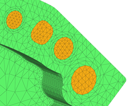
- Patch in separate collector
- Organize newly created patches in a separate part.
- Remesh after cap
- Remesh neighboring regions of capped surfaces. Turn on if the input has good quality mesh.
- Optional:
On the guide bar, click
-
Perform interactive capping.
- Optional:
On the guide bar, click to define cap
options.
Figure 6. 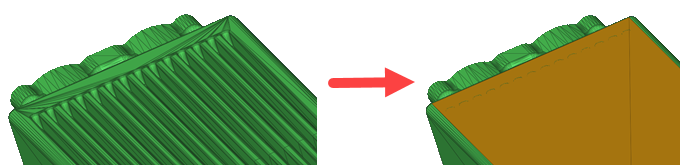
- Optional:
On the guide bar, click
Fill Gaps
-
From the Discrete ribbon, click the tool.
Figure 7. 
-
Select source and target geometry between which to close gaps.
Note: Part and Surface selection is more user friendly – but it will only create a patch if the resulting patch is not intersecting with input. So if gap patching fails, switch to line selection.
- Optional:
On the guide bar, click to define cap
options.
- Remesh patches
- Remesh neighboring regions of capped surfaces. Turn on if the input
has good quality mesh.
During remeshing, element size, type, and order is determined by the surrounding elements' size and type.
- Organize patch in adjacent body
- To organize the filled/patched elements in a new body, turn on this option. If the gap is shared by more than two parts, then filled holes are organized in the part with the higher number of nodes around the gap.
-
Enter the maximum dimension of holes to fill.
- Consider feature loops
- Consider both free edges and feature edges for gap detection if this option in on. If off, only free edges are considered. This option is only considered for part and surface selection. For line and node selection, this option is ignored.
Tip: Measure the maximum gap you want to fill and define the value here as max width. -
Click Gap Patch on the guide bar
to close gaps.
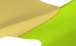
Figure 8. Input 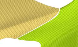
Figure 9. Gap Filled Between Element Sets