Create Derived Regions
Use the Derived Region tool to create enclosed and offset regions around a selection – which can be used to define volumetric refinement levels – or create projected regions in a given direction.
-
From the Discrete ribbon, click the Derived Region
tool.
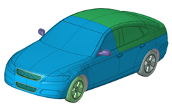
Figure 1. 
-
Select entities to consider.
Note: For this tool to work, your selection should have triangular elements.
-
Click
 on the guide bar, select a
region type, then define any options.
on the guide bar, select a
region type, then define any options.
- Enclosed
- Creates an enclosed region around the selection with specified offset distance.
-
- Enclosure type
- Create enclosures outward or inward from your selection.
- Offset distance
- Distance of enclosure from selection.
- Voxel size factor
- Voxel size when creating enclosed region is calculated from the Voxel size factor (Voxel size = Voxel size factor * Offset distance).
- Part name
- The enclosure is created in a specified new part.
-
Note: To use this utility to create a volumetric refinement region for ultraFluidX, follow these steps:
- Use the Enclosed option to create enclosed regions with the desired offset distance.
- Use the Move tool (by moving nodes) to adjust the shape to cover the wake region and ground.
- Use the Smooth tool to smooth the shape.
- To create the next refinement level zone, select the above refinement region and use the Directional Offset option with a specified offset distance.
Figure 2. Input 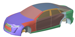
Figure 3. Output with Offset distancce as 75 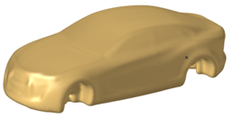
- Directional Offset
- Creates an offset region around the selection with specified offset distance.
- Projected
- Creates a projected region on a defined plane.
-
Click Create.
Figure 4. Input 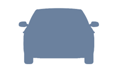
Figure 5. Output with Offset distance as 75