
Associate Nodes to Geometry
Use the Edit Elements: Associate tool to find non-associated nodes, review them, and associate to target geometry.
This is useful in cases where you load CAD and FE separately.
-
From the Discrete ribbon, click the tool.
Figure 1. 
- Make sure Associate is selected on the guide bar drop-down.
- Optional:
Click Find.
A scan is done for associated and non-associated nodes. By default, the non-associated nodes are added to the node selector on the guide bar. A legend indicates which nodes are associated and to which geometry entities.
Figure 2. 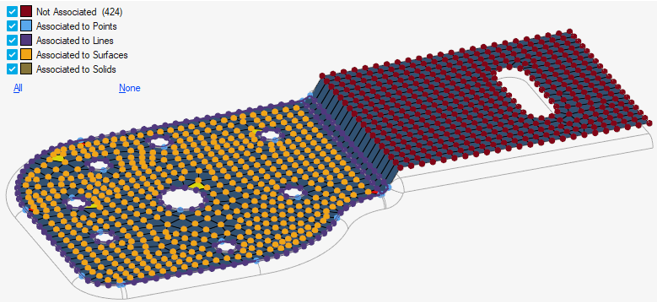
To reset the preview, click
 next to the Find button or uncheck all the boxes in the
legend.
next to the Find button or uncheck all the boxes in the
legend. -
Associate nodes in one of two ways:
Option Description Automatic - Keep all non-associated nodes that were found or clear the selector pick a sub-set.
- Provide an associate tolerance either in the microdialog or the options menu.
The tool will automatically identify the underlying target geometry and associate selected source nodes.Tip: On the guide bar, click and
select Override Node Association to
reassign nodes during automatic association.Note: In the case of dirty geometry, such as distorted surfaces or oversimplified geometry, automatic association might fail for local regions. In such scenarios, it is recommended to select source and target to accomplish association.
and
select Override Node Association to
reassign nodes during automatic association.Note: In the case of dirty geometry, such as distorted surfaces or oversimplified geometry, automatic association might fail for local regions. In such scenarios, it is recommended to select source and target to accomplish association.Manually - Keep all non-associated nodes that were found or clear the selector and pick a smaller sub-set.
- Check the Choose target option on the guide bar.
- Choose a single target entity (solid/surface/line/point).
- Click on the guide bar to define the associate and snap tolerances.
- Associate tolerance
- In the case of manual association, you must
provide an appropriate associate tolerance. Nodes
which are out of tolerance are excluded from
association. Auto-association works on the logic
of matching topology, nodes/mesh, and its
underneath CAD.
Figure 3. 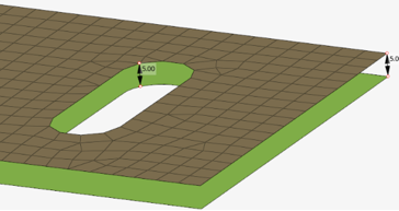
- Snap tolerance
- Distance between nodes and closest vertices. In
case of manual association, you need to provide
the node snapping tolerance. However, in case of
auto-association, the snap tolerance is
automatically derived.
Figure 4. 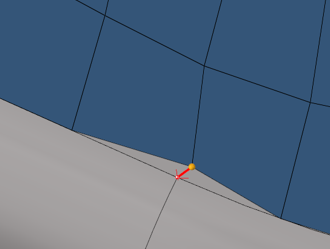
Global “tolerance” is not used here, meaning selected nodes are always associated/re-associated to selected geometry entities.
-
Check the Move nodes option to project source nodes onto
the target entity along with the association.
Figure 5. Input 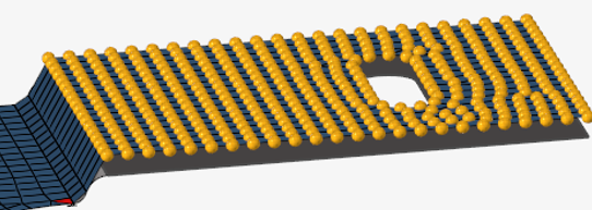
Figure 6. Selected nodes are associated to underneath surface without moving nodes 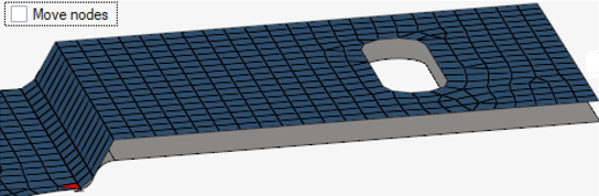
Figure 7. Selected nodes are associated to underneath surface and nodes are projected onto it 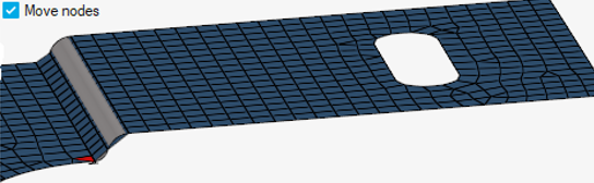
-
On the guide bar, complete one of the following:
- Click
 to apply and stay in the tool.
 - Click
 to apply and close the tool.
 - Click
 to exit the tool without applying.
- Click
Disassociate Nodes
- Change the drop-down on the guide bar to Disassociate.
- Select the surfaces or solids on which nodes and elements should be disassociated.
-
Click one of the following:
 - Apply and stay in the tool
 - Apply and close the tool
 - Exit the tool without applying