Valve Seat
![]()
Dialog Box
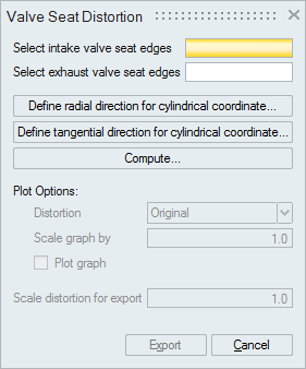
This tool helps to determine the radial distortions in intake and exhaust valve seats corresponding to a single combustion chamber.
User Input for Valve Seat Distortion Analysis in SimLab
Valve Seat Distortion can be carried out in any results file having displacement results. User has to specify the following information for carrying out the analysis.
Select intake valve seat edgesSelect the edges of two intake valve seats.
Select exhaust valve seat edgesSelect the edges of two exhaust valve seats.
Define radial direction for cylindrical coordinateThis direction will be used to determine the R direction of local cylindrical coordinate system which will be created automatically for all the edges of the seats.
Define tangential direction for cylindrical coordinateThis direction will be used to determine the theta direction of local cylindrical coordinate system which will be created automatically for all the edges of the seats.
Types of Plots available in SimLab Valve Seat Distortion Analysis tool
The various types of plots available inside of SimLab are:
PolarThis plot is used to visualize all the distorted valve seat edge profiles in a single plot.

Following types of distortions can be visualized:
- Original
- True distortion - Expansion and Eccentricity removed
- True distortion - Eccentricity removed
- Original distortion
This refers to original radial distortion/deformation of the cylinder bore directly read from the results.
- True distortion(Expansion and Eccentricity removed)
True distortion = Original distortion - (0th order distortion + 1st order distortion)
- True distortion(Eccentricity removed)
True distortion = Original distortion - (1st order distortion)