Bore
![]()
Bore Distortion Analysis
This tool helps to determine the various orders of distortion from displacement results associated with the grid points of the bore surface. These distortion orders were found by representing the bore profile by means of Fourier series and evaluating the Fourier series by employing Fast Fourier Transform.
Calculation Method
The following Fourier series expression is used in determining the distortion orders:
ξ(Φ)=r0+ΣAkCos(k(Φ + δk)) (1)
Where, ξ(Φ) denote the bore shape, Φ is the polar angle, δk is phase angle, r0 is the bore radius and 'k' refers to the order of distortion. Eq(1) is referred from a journal cited in Reference [1]. For calculating the individual orders of distortion, the above equation is simplified as below:
[Bore Shape]k=r0+(AkCos kΦ + BkSin kΦ) (2)
Methodology
SimLab adopts two methods for performing bore distortion analysis. One for analyzing Iso Meshed bore surfaces and another for Non-Iso meshed bore surfaces (partial cylinders, bore surfaces with holes also taken into account in this method).
- Analyzing Iso Meshed surfaces:
In this method, the distortion orders were found out by taking into account of nodes(grid points) of the selected iso mesh surface.
- Analyzing Non-Iso Meshed surfaces:
In this method, nodes were created internally both in axial and circular directions. The number of divisions along the axial and circular directions have to be specified by the user. The internally created nodes were used for performing bore distortion analysis. The displacement results for these nodes were obtained by shape function interpolation.
User Input for Bore Distortion Analysis in SimLab
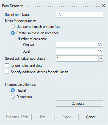
Select Bore Faces
Select the Bore faces to be analyzed. Multiple faces can be selected but they should have same axis.
Mesh for Computation
Select the calculation methodology either as Iso Mesh or Non-Iso Mesh. Use Iso Mesh method if the bore face is perfect iso mesh. Use Non-Iso Mesh method if the bore face is free mesh and also if it contains holes or any other discontinuities.
Cylindrical Coordinate
Select the local cylindrical coordinate system corresponding to the selected bore face.
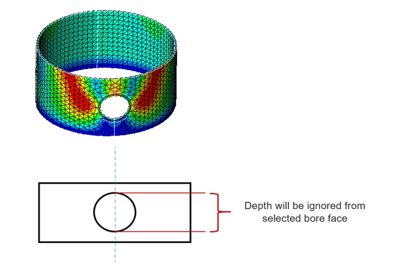
Ignore holes and slots
This option is used to skip the depths at which holes and/or slots are present in the selected cylindrical face. It is supported only with the "Create iso mesh on bore face" option.
Specify additional depth for calculation
Specify the depth at which the circle graph need to be plot.
Interpret distortion as
- Radial - distortion values will be based on the radius of the selected bore face
- Diameter - distortion values will be based on the diameter of the selected bore face
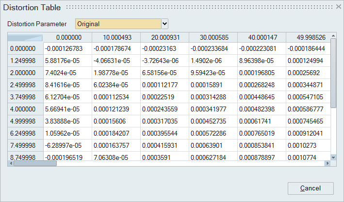
Distortion Table
Table shows calculated distortion values for selected faces
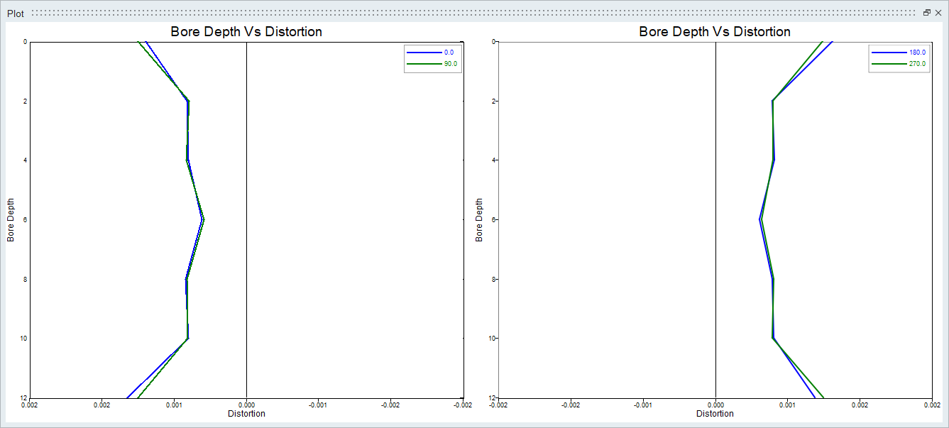
Distortion Plot
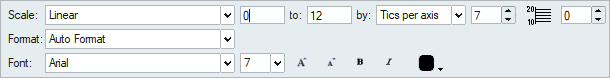
Simlab bore distortion is integrated with the new tool for graphing. It allows user to do the following customization.
- Zoom in / out
- Multi color
- Font size and style
- Title and legend edit
- Grid ON / OFF
- Axis limit
This new plots can be enabled by turn on the "Enable new graphing tool" toggle in Preferences.
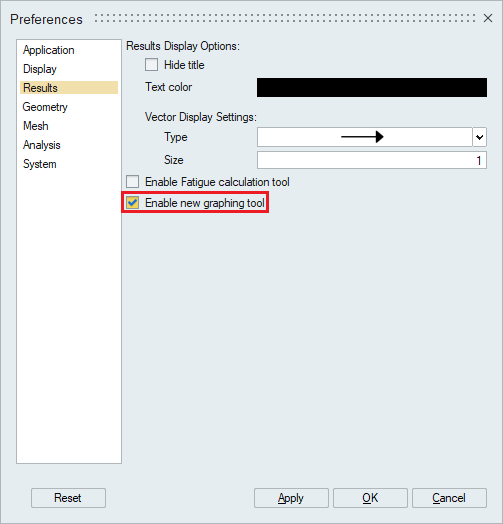
If this toggle is turned off, graphs will be drawn with the older method.
Various Type of plots of bore distortion
Various types of plots available in SimLab-bore distortion are:
- Circle
- 3D Deform
- Vertical View
- Circularity
- Fourier Coefficients
- Diametral Distortions
- Vertical Cut Plots
- Circle
This plot is used to visualize the distorted bore profile at a particular depth from a reference cylindrical coordinate system in polar coordinates.
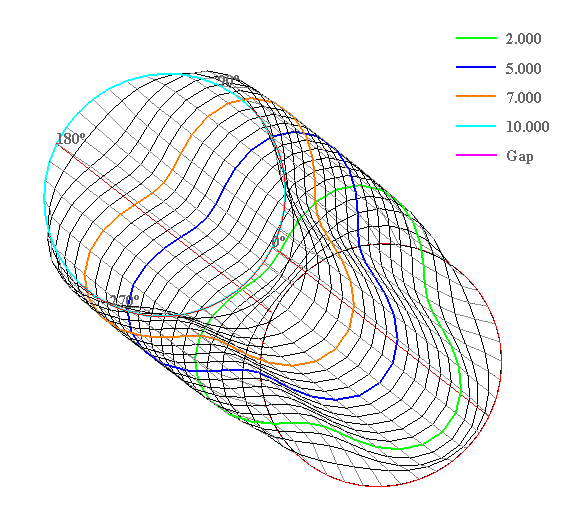
- 3D-Deform
This plot is used to visualize the three dimensional distorted bore shape.
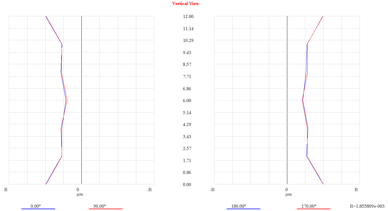
- Vertical View
This plot is used to visualize the distortions along the axial direction at four different angular locations spread at an interval of 90 degree.
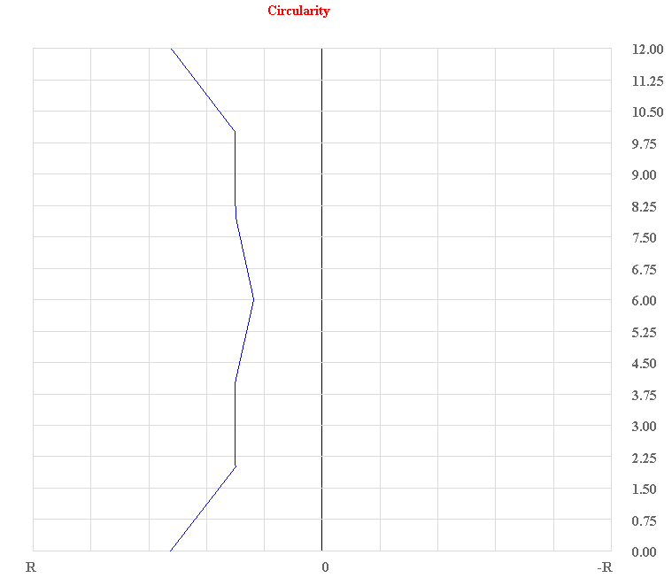
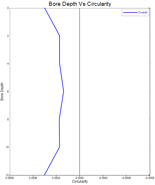
- Circularity
This plot is used to visualize along the axial direction the difference between the Maximum True Overall value and Minimum True Overall value at each depth.
True Overall value at an angle is the difference between the Maximum distortion among the various orders of distortion (excluding zero and first order distortion) and the Minimum distortion among the various orders of distortion(excluding zero and first order distortion) at the respective angle.
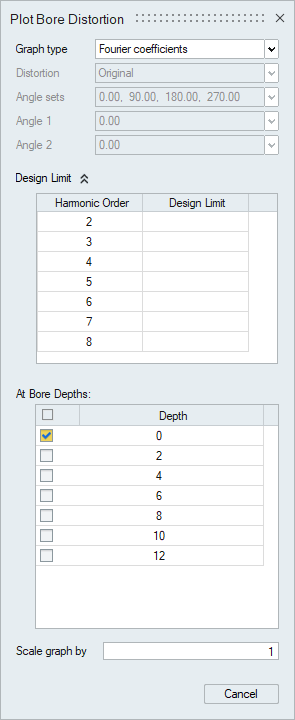
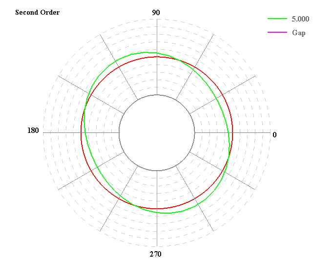
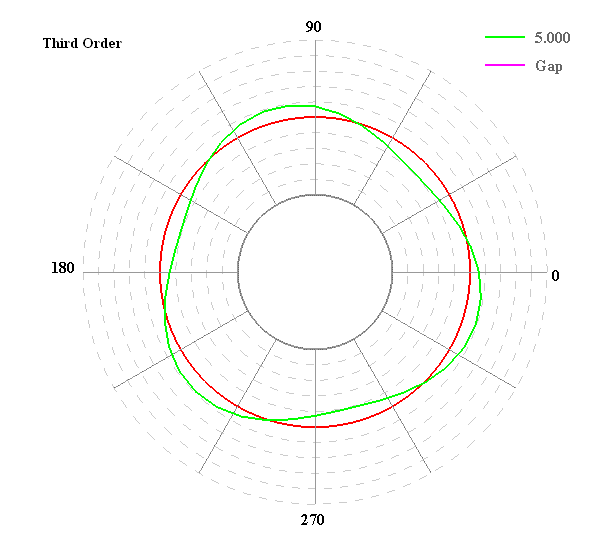
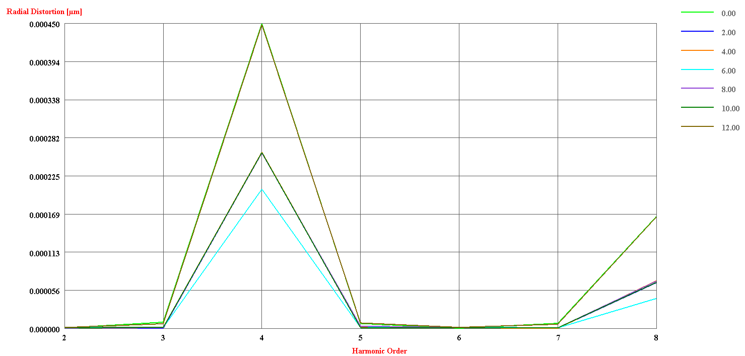
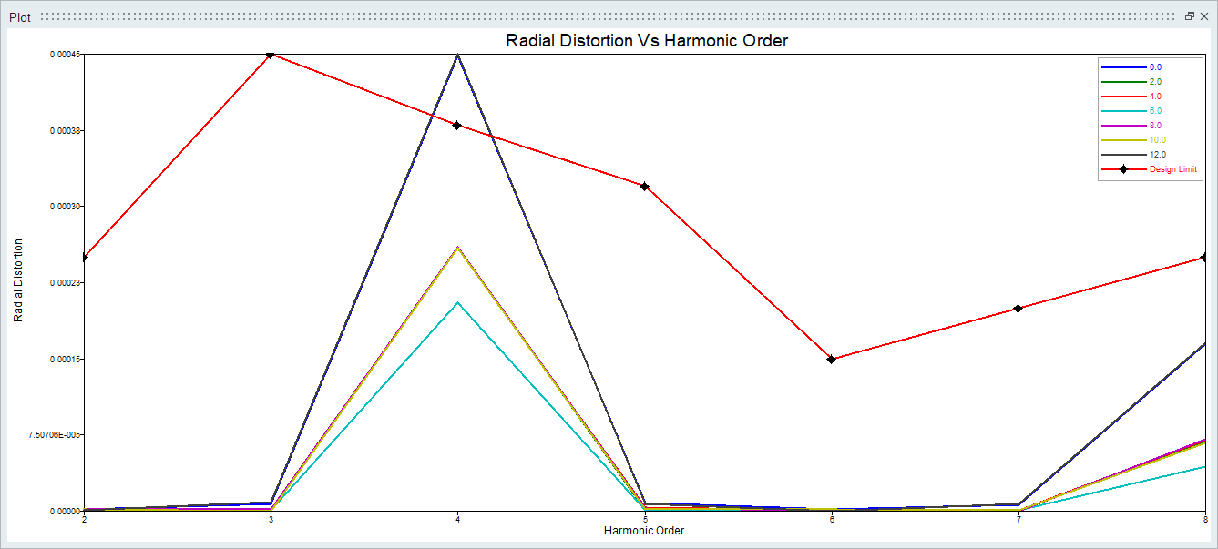
- Fourier Coefficients
This plot is used to visualize all the bore distortion orders/fourier coefficients for user specified depth.The design limit values of Fourier coefficients can be specified to compare the distortions.
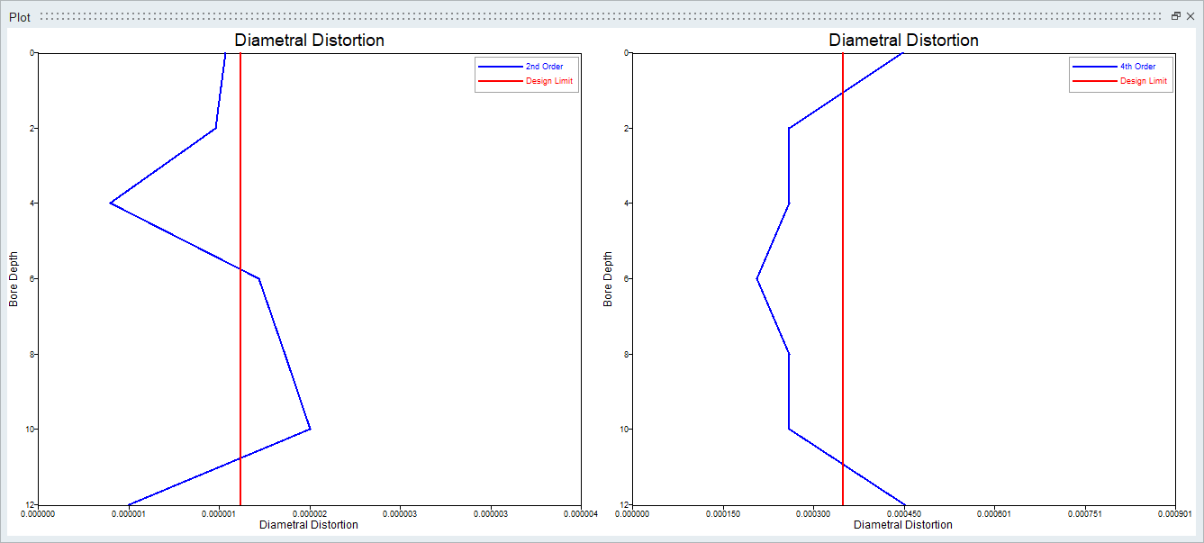
- Diametral Distortions
This plot is used to visualize user specified distortion orders/fourier coefficients along the depth of bore. The design limit values of Fourier coefficients can be specified to compare the distortions. This is plot can be drawn only when the "Enable new graphing tool" is turned ON.
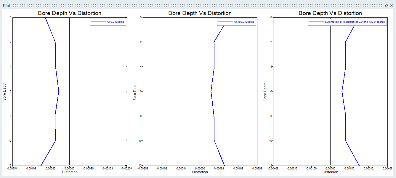
- Vertical Cut Plots
This plot is used to visualize the distortions and summation of distortions along the axial direction at two different user specified angular locations. This is plot can be drawn only when the "Enable new graphing tool" is turned ON.
Definition of Terms used in various plots
- Original distortion
This refers to original radial distortion/deformation of the cylinder bore directly read from the results.
- True-OverAll distortion
This is calculated for each angle and it is the difference between the Maximum distortion among the various orders of distortion (excluding zero and first order distortion) and the Minimum distortion among the various orders of distortion(excluding zero and first order distortion) at the respective angle.
- True-Zero Order distortion
From equation (2), the zeroth order distortion is obtained as
[Bore Shape]0=r0 + A0All the other orders of distortion from True-First order upto True-Tenth order are calculated by the following expression (without considering the shift in the bore axis)
[Bore Shape]k=r0+(AkCos kΦ + BkSin kΦ)
Where, 'k' range from 1 to 10.
-
True distortion(Expansion and Eccentricity removed)
True distortion = Original distortion - (0th order distortion + 1st order distortion)
- True distortion(Eccentricity removed)
True distortion = Original distortion - (1st order distortion)
- True distortion(Summation of second, third and fourth order)
True distortion = (2nd order distortion + 3rd order distortion + 4th order distortion)
- This new graphing tool feature is not supported for Abaqus(odb) results.
- Reference: [1].Teimuraz Bardzimashvili,James F. Kelly,Elene Romelashvili,“Distortion Inside a Piston Bore”,2004.